Leaderboard


Popular Content
Showing content with the highest reputation since 04/13/2024 in all areas
-
Unfortunately, most of these kinds of decisions are based on $$$ instead of the things you note.6 points
-
It can be done effectively... it just has to be approached in the right manner. The #1 issue with inspecting a part on the machine that produced it isn't that the machine is checking itself, it is that the connection between the coordinate system that manufactured the part and the coordinate system that is inspecting the part isn't broken. You MUST break that connection in order to get an accurate measurement. On a 5-Axis machine with a FANUC control, that means having G68.2, G54.4, machine parameters set correctly, AND the probing software that supports probing with those functions active. Don;t have ALL those things squared away and there WILL be trouble in paradise.4 points
-
This is one of the many areas I believe Matsuura is FAR superior to the toilet bowl lovers in machine design. Matsuura can get closer to the pallet center with the head/spindle. Doing this allows you to run shorter tool assemblies and it requires shorter work holding to get ot he part. All that to say a more rigid machining setup = the best metal removal scenario possible. In the MAM series they offer the MAM72-35V, MAM72-42V, MAM72-52V, MAM72-70V, and MAM72-100H. Then in the CUBLEX series there is a CUBLEX-35 and a CUBLEX-63. There was a CUBLEX-42 but I believe they discontinued it. 350mm, 420mm, 520mm, 700mm, and 1000mm respectively. The number after the dash is the CM value of MAX pallet Changing swing diameter essentially.3 points
-
Ref ISO9001, there were 7xmandates when we got approval (2x man shop) back in 2007. It (9001) was updated in 2015 and the mandates were changed, but at the time I remember the assessor saying he knew of 1x UK company that was a 1x man band who had got approval and another company whose manual was 2 pages....the manual then consisted of flow downs to other documents which specified/controlled the said mandates. My manual was total of 35 pages, which was very padded out as the 1st half was design requirements and the tail end were copies of the things like CofC, Job Traveller, Invoice etc - I reckon I could have consolidated it to 15 pages if I'd removed the padding, as the design stuff was only for "sales" as we weren't "ISO approved" for that. But yes to quote Margaret Thatcher...."sometimes it is best to be specifically vague"....ie if you state ail job cards need sign off in ink, just state ink. If you state black pen, someone will use blue and you'll unnecessarily fail the audit (simplification but you get the idea). AS9100 (aero) was the next step with the only real main difference (at the time) being stock control - you had to control every inch of material, every rivet and screw and washer etc - ISO9001 you could just state (for the same material batch number) job 12345 had 10", job 12346 had 20", job 12347 had 10", of material batch number AXXXX and that was okay. AS9100 took that further by stock control monitoring so you had to detail incoming delivery of batch number AXXXX was 50", and you used 10, 20, and 10" on the 3x jobs above, so you now have 10" still left in stock (unsure of exactly how you get around tolerance of cutting and width of saw blades....for billets, washers, screws (ie "items") it's easy). Initially...."getting approval" can seem daunting, but if you break it all down to bite size chunks, the dauntingness rapidly diminishes. Certain practices you should really be doing anyway - such as material batch traceability gauge control and calibration, and office things like "contract review" which catches things like repeat purchase orders which have a revision/change, so you don't make at previous (old) issue.... Overall, it helped focus my business and got a 2x man band approved to be Tier 1x supplier for some major OEM's. Which then allowed us to grow but with control and focus.3 points
-
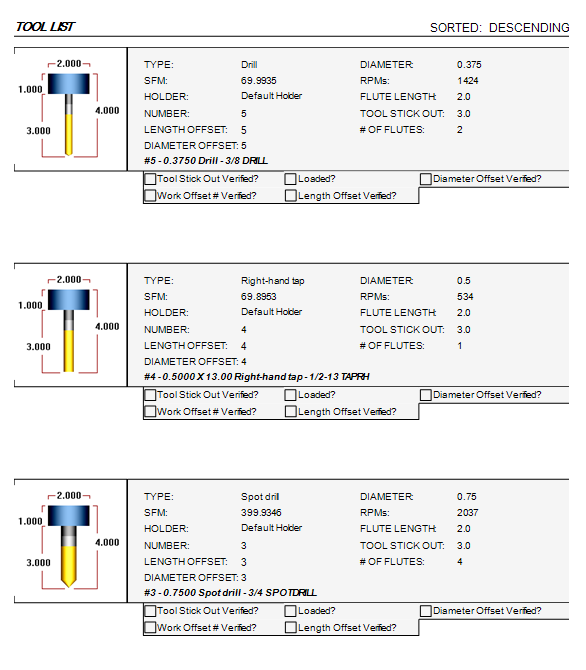
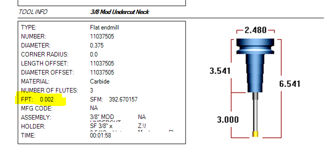
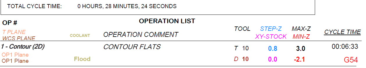
Thanks for all the replies. I ended up going with the Mill 2 setup sheet and I got a lot of fields down: Here you can see the checkboxes I added, plus SFM and RPM (thanks rgrin!). I think my main problem now is styling. That being said, I wanted to say that I do understand this a little better. When people were saying that the naming convention was important, they weren't kidding. The name in parentheses is the XML tag that the interpreter goes down to. It's almost like you're peeling back layers of an onion, except you can't really go back up, but you can dig deeper down. Another thing I'd like to say is that I still have 0 clue how to use the scripting section. If anyone has any experience with that, please advise. I think it would be a great idea to write some unofficial documentation on this so that everyone can start writing ActiveReports, because when you start to dig down deep and really learn how it works over the course of a few weeks or so, you really start to have fun making things your own and figuring stuff out. Suffice it to say, I got most of my setup sheet done thanks to this forum and thanks to everyone's help. I really appreciate it.
 3 points
 -
Ask the pushers if they want the machines making more chips or checking parts. Maybe your management team thinks differently, but my management team always wants to make more chips. Some of them may not understand much about manufacturing, but they all understand more chips = more parts = more $$ ...food for thought, a CNC can do a CMM's job but not visa versa.3 points
-
Yeah because of what I just mentioned above. When the above is done with a NIST Traceable artifact then the process is not just using the machine to inspect the part it is the process that is support the device which happens to be a CNC Machine. The device collecting the measurements doesn't matter at that point since the process to ensure what is collecting the measurements is validated and verified all is good. A CMM that is not correctly calibrated is not better than a machine tool that is not calibrated correctly either.3 points
-
Well I learned last week a major very respected builder does their machine calibration services using levels and squares not an interferometer. The issue was our programming process used was called into question. Print states one thing, but then 20 other things state 20 other things. Print is the authority unless some inspector decides no they want a +/-.0005 on a part with a +/-.010 wall thickness on the print. Or a 16 finish when the print calls out 125 and add hundreds of hours of processing time to the project. Cut 6 pockets the same exact way and 2 of the 4 are acceptable, but then as we get to longer tools the deviation between the two tools doing the work became greater. Root cause analysis looks into the root of the problem. Machine has not been calibrated in over a year. I happened to be onsite when they were going through the machine calibration and what an eye opening experience that was. Levels and squares with a spindle gauge. No external way to verify the machine is going where it is told to. This is the extent of the full volumetric machine calibration process. I called James and make sure I hadn't lost my mind and was an internal interferometer installed on the machine in question I was unaware of. NO NOT ONE HE SUPPORTS and he was unaware of one being installed either. We both agreed even it one was that at someone point would have to be calibrated. Why is this an important topic of conversation and how is it related? Here is some light reading for those that take their jobs seriously. All the hates keep on hating. Machine tool calibration: Measurement, modeling, and compensation of machine tool errors There is too much to quote that is important.3 points
-
I had the file checked and I was told was suspected pirated software used to create the file why I never responded back.3 points
-
Support should be the #1 consideration when buying a 5-Axis machine. Much like a multi-tasking lathe support will make or break that machine. You could buy "the best" (whatever that is) machine but when the good for nothing AE shows up to train you, he (or she) has no clue about cutting parameters to utilize the machine to maximize it's capability, it's going to be on YOU to figure out. Oh sure, they'll tell you "... that's the CAM system's responsibility...", and it is, but only to a certain extent. When they cannot explain to you the role of point spacing, cut distance, and tolerance, and how it relates to machine performance, you ARE in for trouble.3 points
-
Whether or not inspecting on the same machine that made the part will meet your needs, will depend on your needs. If you want to do it properly, you should meet the same bar as for other measurement methods; get your machine laser / ballbar calibrated, do a measurement repeatability and uncertainty test, etc., and make sure that your uncertainty is less than 1/10 your tightest tolerance. You can include measuring a gauge block / pin / ring as part of your inspection process to warn you of any calibration drift, thermal expansion issue, or other problem.3 points
-
Component size....number of different part numbers to make....required geometric tolerances....tool matrix size....level of required automation....control compatibility with rest of shop....programming SW.....verification SW....etc etc.... As THEE cncAppsGuy has said, TOTAL support is #1 as you're jumping into new water with the 1st machine. Of which, successfully implemented, should lead to your 2nd machine. But it's a BIG jump from a Vert or Hori....daunting if on your own with the hot job sat waiting for you! Knowing who you can then reliably phone, will make your decision far easier IMHO.2 points
-
Also, if you've got the inspection stuff squared away, it's easy peasy to generate reports, csv data, etc... If you can imagine it, you can format it, and generate reports.2 points
-
There's also less handling if you can get in-machine-inspection working right, reliably, and efficiently.2 points
-
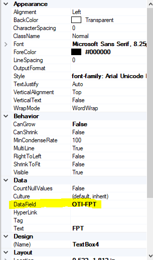
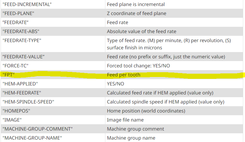
OTI-FPT will give the chipload from the tool description. OOI-FPT or just FTP will give you the operation chipload. I would suggest just adding a field in the operation file so it generates for each operation. I recently updated my sheet to add some fields. I.E. XY stock Z step Edit: added a pic
 2 points
 -
Adding non manufacturing time adds TAKT time. Added TAKT time = higher cost. That said, WIP = Inventory. Inventory = Money. Money = Taxation Parts in inspection = WIP therefore there's a cost no matter where the part is within the factory. If you can integrate and automate processes you can bring down the labor component of part cost. "There are no perfect solutions, only compromises." Thomas Sowell2 points
-
Took a quick look and it seemed easier to make a video than to write it all out (plus, I'm pretty much out of space to upload pictures and files!), hope that's okay:2 points
-
I looked into this and it looks like this escaped the What's New, but the description above is accurate. It's hard to quantify the changes you'll see other than "It does better in some scenarios". Because the results are different enough that it could change existing Swarf toolpaths substantially, they chose to leave in place the old method (legacy) as an option and default to the new Automatic in new paths.2 points
-
For 90% of people, the CIMCO add on will be way less setup pain and get you there faster, cheaper, and easier utilizing the I+ macros already set up on the machine. For 10% of the people, I haven't seen anything else on the market give the ease of use of setting up complex logic (multiple nested If/Then/Else logic) like P+ can do. Inspection+ are the macros that ship with the probe on your machine. If you use the GoProbe app on your phone (or the Renishaw manual) to enter, say, G65P9901M2.D0.5S54. to probe a .5" bore, that's Inspection+. Productivity+ was developed by Renishaw as a stand alone program (yes, you can buy just P+, not integrated into Mastercam!). The problem was they can't trust the I+ macros to be the same everywhere, that no one edited them, and that they could support all the logic they wanted so they developed the P+ macros. You'll have two sets of macros loaded onto your machine, two sets of calibration data in the parameters, etc. P+ coming out of Mastercam will ONLY use P+ macros.2 points
-
Since the spindle is cantilevered out so far, if the front of the column gets warmer than the back, or asymmetric heating of certain other members takes palce, it will arch and lift the tool much more than the linear thermal expansion rate. This problem plagues the whole UMC line, in combination with poorly done thermal comp software. To fix it with thermal comp, they would have to add a bunch more thermocouples in several locations, and have a much more complicated compensation model. What I've heard works best on these machines is to turn off the thermal comp, and take every measure you can to keep the temperature of the machine constant within a very small window. For comparison, I get less than .001" Z change over 20°F on my CM-1's.2 points
-
In fact, the GUI is setup so that it requires 2 presses of the cycle start button. The reason being is in case you do not at first place the tool over the button and 10MM above. Initiate the cycle, press cycle start. You can't see it but there is an M00 active. Without pressing reset, go to HANDLE mode, move your tool in position, go back to MEM mode and press CYCLE START again. The process will proceed.1 point
-
I think this worked pretty good.
 1 point
 -
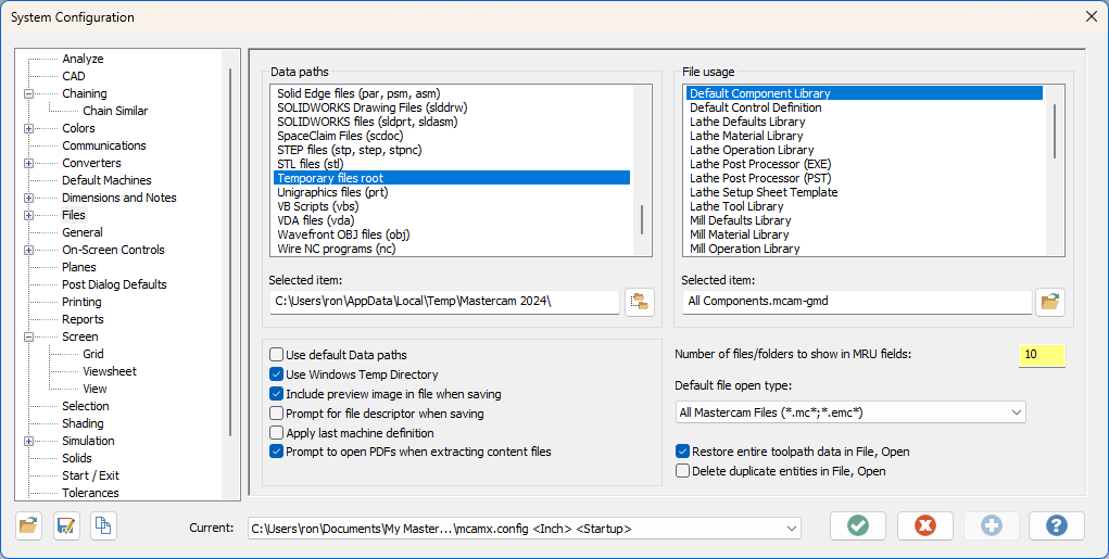
Check antivirus software is not tying up your temp folders doing scanning. I have to disable that or I will get the same error. The other option is to make your temp folder a safe place on the computer.
 1 point
 -
I would think not. Will need to purchase a custom post to get what you are asking for. Only so much a free post will get you.1 point
-
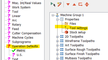
Hi, this must be no problem. Control Definition - Operation Default - Tools Settings and that's all. Good luck!
 1 point
 -
Tagging this post. I watched Colins's entire youtube course on this and ended up with a pretty nice post.1 point
-
@James - great comment ref your #1 above. I would also add the obvious that part shape material and workholding comes into it too. Measure the part xxxx on! Unclamp the part and distortion.... And Ron - Ref many Inspectors and their job choice...."If you can't do it, View it"1 point
-
That's not really a concern. The collision detection only works to tilt the tool. Actual motion (the fact that this will cause the B to tilt) is only really a function of the post & machine definition. The part itself is stationary from the toolpath calculation side, which is why when you backplot it (not machine sim!), it shows the tool tilting. If you have the A Axis setup modelled, you can simply select it as part of the Collision Control > Avoidance Geometries selection and it'll be fine.1 point
-
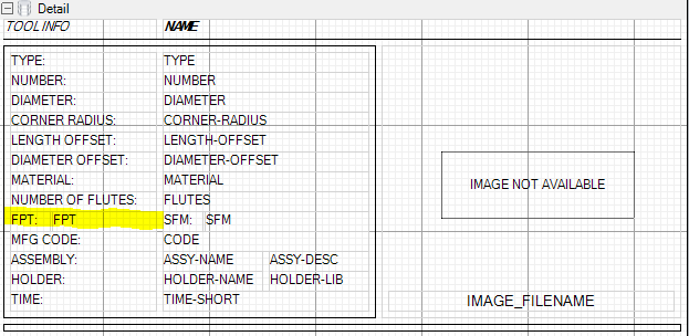
I'm fairly lost when it comes to setting up new sheets in active reports since I've got mine setup the way I like. It appears the default setup sheet (mill) report has FPT displayed. You might be able to track down how they did by going through that one? In the -Setup Sheet (MILL-TOOL) rpx file, they have FPT datafield listed as OTI-FPT. Maybe try that?
 1 point
 -
Support is the biggest concern with dmg without a doubt. Matsuura mam-52v system looks like it it would fit the bill as well. Ill check on availability. Seems like that is the biggest factor that we have been running into.1 point
-
I would agree that Hermles spindles is their weakspot. I'm not a fan of greased spindles and moving to their higher RPM air oil spindles loses alot of power. Unfortunately, I can't compare their performance vs high performance as we don't have one of their high performance lines. I also am not a huge fan of their automation as it's thru the main cabin door which kind of sucks from an ergonomics stand point. If I had to pick my favorite MTBs right now, it would be Yasda, Makino, Matsuura, Hermle, and Okuma. I think they all have their pros and cons and you just need to figure out which ones you prefer and which ones does the work you need it to do the best.1 point
-
Hello, Yes, that's what I have been doing, was just wondering where I could the server, password and username info. Thank you.1 point
-
Personally, I'm an Okuma guy. We bought an Okuma MU1000H in 2013 and have run it hard 24 hours a day 6 days a week for a decade. It has been such a good machine we bought a 2nd one in 2023. With a 170 station tool magazine and a 2 station pallet setup they are consistently the most productive machines in the plant. A 6 station pallet changer is available for these, but that would take up too much space for us. We struggled to find room for the 2nd machine. They build vertical trunnion machines as well from 4000mm tables to 8000mm. Okuma 5 axis machines1 point
-
You should be able to pull the Feed per tooth straight from the Mastercam operation.
 1 point
 -
Thanks Dylan, that's good information.1 point
-
Saving as a parasolid- (.x_t) is the best solution, as both Mastercam and Solidworks use the parasolid kernel for modelling and there will be no translation or transformation of data when saving out to, and opening from, the parasolid format. Depending on the version mismatch between Mastercam and Solidworks, you may have to go into the Options box in the save dialog to set the output Parasolid version to a lower version that is supported by the older of the two packages you have installed.1 point
-
That's perfectly normal LOL serious though, back in the day I was part owner of a small shop We had 2 Hass VF1's with 5C collet indexers.. We made boatloads of money with those 2 machines.1 point
-
Asking questions on the Mastercam forum is a lot like shouting at clouds, so I thought I'd try here. The MC2025 PB3 Swarf Toolpath/Advanced Control now has Advanced and Advanced (Legacy) Obviously there is something different about the new Advanced or they would not have let Advanced (Legacy) behind. Does anyone know what the difference is? I'm doing a new project and getting excellent results from the Swarf toolpath. but I really can't detect any difference between Advanced and Advanced (Legacy)
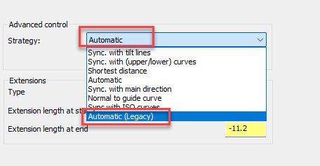 1 point
 -
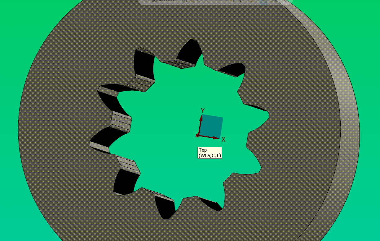
As always when you need help, ask the experts. Thanks guys!!! I'm using the new automatic on a vane I'm doing as it looks really good in MC Backplot , Postability Machine Sim and Vericut It will be several weeks before it gets a real world test on our Okuma MU-1000H. I'll report back then.1 point
-
Yep, correct. It will be updated with the latest MW documentation upon 2025 release- not as helpful for Gcode now1 point
-
The documentation is actually available on Mastercam.com, under the Learning- Documentation area: Downloads – myMastercam The "Multiaxis Help" files are the ones you're looking for. Of course, be aware that not everything in those files is implemented or interfaced as shown.1 point
-
I had to search for the latest release of MW documentation: ------------------ Automatic - Contact lines are placed in a way primarily minimizing the undercut to the target geometry and secondarily minimizing the allowance to the target geometry. In case the target geometry forms a ruled surface, this strategy will try to create a toolpath with neither undercut nor allowance. In case the target geometry is no ruled surface, it will try to create the toolpath with the least undercut and allowance possible. This strategy is intended as the default, first-shot strategy. It contains a number of heuristics to create a reasonable tool axis tilting on a wide range of input geometries. Optionally, users can define tilt lines to fine tune the tool axis alignment in specific areas ----------------- Automatic(legacy) - tries to place the tool on the swarf surface in a way that minimizes the area between the contact line from the lower to the upper curve and the swarf surface. Since the swarf surface is sometimes a parametric freeform surface (with double curvature), the area is not necessarily zero. ----------------- Sounds like they improved a some of the cases where automatic choked up, but are acknowledging that it might break some other situations they couldn't test for?1 point
-
Might be worth checking out this thread: From what I remember there was a lot of good stuff in that one.1 point
-
I would not recommend inspecting a part using the same machine that made said part. Been there, done that.1 point
-
the only way to do this is to save the deburr operation backplot as geometry then do a C axis face contour on that geometry then the post will post as C and X or if using G112 it will output correctly1 point
-
The alternative is to reprobe frequently, up to every toolchange or even every cut if the tolerances require it.1 point
-
Ball Lock® (jergensinc.com)1 point
-
Just ran some unattended parts with some tight tolerance 5 axis features and used probing to make it all possible. The parts had a +/-.0005 Dia bore that had to be machined from both sides. Good ole haas love to heat up and move around so relying on just COR for this wasn't gonna work. I machined half of the bore from one side, spun it 180 and did a wash down on the bore with that tool. Grabbed the probe and then from this side reached through to the the bore I just did on the opposite side, set a Work offset for just this feature, checked the size and position(more for mixxxx/chips hitting the probe. Then came and machined the other side of the bore. At the end of the program I had the probe check the whole bore from one side for size and position. This worked great. Both sides were within .0002ish from side to side and only drifted .0001-.0002 in size throughout the 30 part run (verified with a cmm) In process probing IMHO is way underutilized compared to the overall payback. I'm probably going to check more features as an in-process check when running unattended now.1 point
-
@Bob W. Great post, thank you. At my job shop we are about to embark on our "lights out" journey. As with most stuff, everyone around me is saying "now that we bought the machines, we can run lights out" without *really* understanding all the variables. 100% of our multiaxis mill parts have been set up and ran by me, and now I'll probably be programming full time trying to keep these two pallet mills fed with parts. (but I'm sure if a tricky 5axis part is in the pipeline I will want to personally set it up) I have operators at my shop who load drills into dirty er collets with rust on the taper, and don't even bother doing a quick S200 runout EYEBALL check haha. These are the guys going to be setting up my stuff?! oh lawd I also have setup sheets with specific holders and specific stickouts and it baffles me that sometimes they just straight up ignore it. Yeah, go ahead and put that 1/32 endmill stuck .500" out in a side lock holder, sure. Wonder why the finish sucks? My *manager* was running my machine while I was programming and I gave him a torque wrench and told him the spec I was using,... I walked out 30 min later to see him using a regular wrench on the vise. makes me want to pull my hair out. Yeah, it's an OP10 and the part would be fine, but it's the principle... Sooner than later he's going to do that and it won't be fine, or the parts will vary in flatness/thickness/whatever. I could go on for hours lol. Needless to say it's got me excited, and equally nervous. So I'm watching this thread like a hawk looking for tips and tricks1 point
-
bin it.1 point


.thumb.jpg.15afa8dbfcde0167893a4a297d335e0b.jpg)