Leaderboard


Popular Content
Showing content with the highest reputation since 05/19/2018 in all areas
-
LOL! We are trying something new, a social experiment in our shop I thought some might find interesting. We currently have redundancy in every department in our shop. We have multiple good machine operators, multiple physical inspection experts, multiple CMM programmers, etc... What we are doing as a shop for the month of August (trial run) is half the team will work Monday-Thursday and half the team will work Tuesday-Friday with each team working four 8 hour days. The fifth day will be paid at 8 hours so essentially they will be given 52 extra days of paid vacation if this is sustainable. My goal is to hit our monthly deliveries and sales targets and so long as they can manage that this arrangement will continue. The ball is in their court on this. If we get the work done there is no additional cost to the shop, our payroll will remain unchanged but the employees will have an additional 2.5 months per year (52 days/ 5 days per week = 10.4 weeks) to enjoy life. We are currently doing well and profitable and we leverage technology to the hilt (cells, robots, etc...) so the shop runs well with a skeleton crew. Monday and Friday will be light but we should be able to shift our work flow to accommodate this. I really hopes this works well because my ultimate goal is to create solid employee loyalty and facilitate a better work-life balance for them. I will keep you posted on the outcome. I'm thinking this will also make hiring pretty easy as well21 points
-
We build a bulkhead for a business Jet. It's flat on one side with pockets on the other. In the past, we have scraped many out of TOL. from warpage. Recently, I re-programmed this part with success and little distortion. Constellium, our material supplier was impressed with the part and asked to purchase one of these to take to the show. Of course, we requested permission from the OEM. They did grant permission as well as instructions to modify the part and rivet a name plate. This was displayed in there area of the Paris Air Show 2023. I am proud of this work. Thanks for reading, Steve Austin
 21 points
 -
Take a look at this and see if it'll work better for you. I didn't have much time here between meetings with customers, but I slapped a Unified > Morph on it (Guides would give you approximately the same results). I turned on Smooth corners (so it doesn't do a 90° bend in the corners) and I also extended it. Also, I changed your linking to be a blend in small gaps, so it transitions nicely instead of "direct." The only other change is Op2 is the same as Op1, but I put on collision control for you so it won't gouge the blades.Sample - Unified.zip One other thing you can do is get fancy with trimming the "corners" to make the toolpath smoother, and then do a small toolpath in front of the impellers, something like this: I didn't have time to play that much and I didn't want to leave you hanging until this afternoon when I would have had a chance to do it.
 18 points
 -
Hello forum people! I wanted to let you know that after 9 years here at the helm of Multiaxis and Hole Making, I'm going to let someone else have a turn at the tiller. I'm going to transition into owning a shop nearby in Hartford, starting on Monday. This is my last day @ CNC Software. Thank you all for being here! I've been on eMastercam longer than I've worked at CNC, and I'll be here long after, but I may lose access to this particular account. I'm not sure Cheers,17 points
-
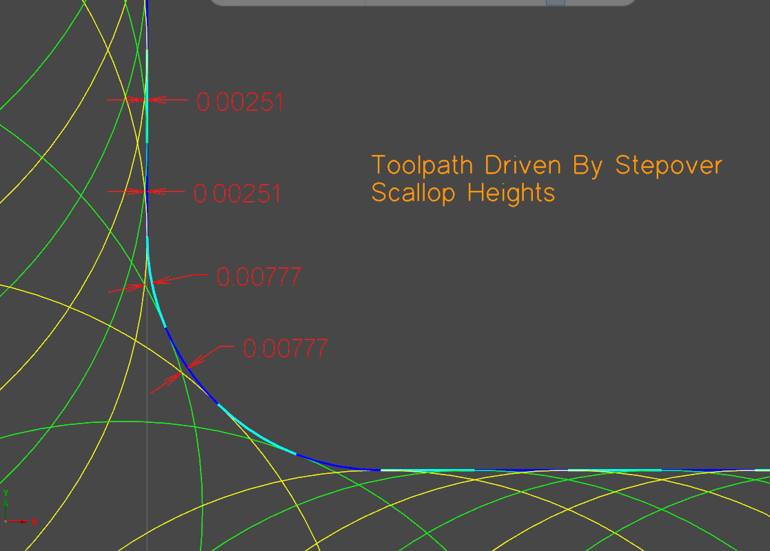
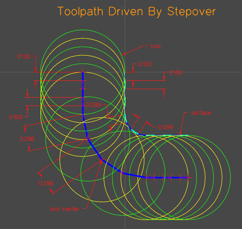
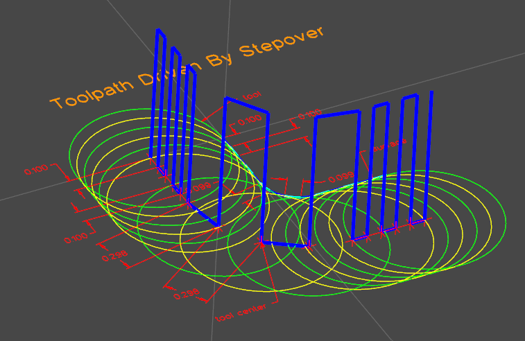
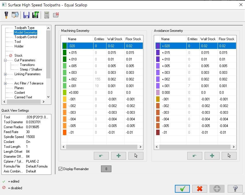
Wanted to do an in depth explanation of this because it took me a long time to figure out when to use stepover vs scallop and why. Tool center and tool contact point are two different things. The toolpath lines we see in backplot are where the center of the tool will be. When surfacing around a radius and driving by stepover, the center of the tool must take larger steps to keep the stepover at the contact point consistent. In these pictures you can see when driving the toolpath based on the stepover, the stepover around the radius stays consistent at .099-.100, but the tool center stepover is much larger around .298. An unexpected consequence of using stepover is the scallops around a radius will be bigger or smaller than scallops left on flat surface. When using scallop to drive the toolpath, you tell Mastercam you care more about the height of the scallop than the stepover. This causes the stepover of the contact point to shrink around outside radii and grow around inside radii. Dropbox Link To File and Pictures (MC2023) Please correct me if there are any mistakes in this explanation. I think I have a solid understanding of this concept but there's always more to learn. Hope this helps!
 15 points
 -
Hum you must not be programming anything then that repeats or you care to go back and look ever again. Levels are key to being a good programmer in my humble opinion. I have taught Mastercam to well over 200 people and in every class I taught, the first thing I always taught them was why and how to use levels. I give someone a 1000 prints and tell them to go put them in a file cabinet. Now they can just stack then in there in less than a couple minutes with no problem. Now I go ask them to pull a certain print. What are the odds they are going to find that exact print? Now I ask them to go pull another print tomorrow or next week. What are the odds they will even remember what or where they were put. Now that person has to go through all those prints to find the correct one. How much time does that waste every time they have to go do that. The programmers levels should be their internal file cabinet for keeping things tracked. You can create a csv file that is a standard template you load in every time you fire up Mastercam. You can have a file you use as a template. There are many ways to keep things organized, but that is the key. It may seems like it takes a lot of extra time to do it upfront, but in the long run saves tons of time and allows not only others to follow your work, but you as well. I am not trying to beat you up I am just trying to give you good advice to help you in this profession. I would never hire anyone who doesn't understand levels and naming them are an important part of programming.14 points
-
and as I Have said at least 100's of times......don't... It uses copious amounts of system resources to visualize a thread. When I import tooling that has threads, the very first thing I do is get rid of the thread. File under, Just because you can doesn't mean you should. JM2C YMMV13 points
-
Yep. I made a little video to show how to do it:13 points
-
My co-worker and I looked at a project several years ago. We both agreed on a cycle time window. Customer had a time study from a competitor that was 25% lower than our time study so the sales guy asked us to take a look at it so we did. We revised our number and figured out a few ways to shave some time with form tools. We dropped 5%. But we said not a second less. So we told the sales guy to advise the customer to put in putative damages clause because there was no way in hell that part was going to be made in that other AE's estimation. They did do that but they went after the sexy quote instead of the honest one. End result; the AE that wanted to be the hero got fired. He was off by roughly the amount we estimated. Basically the customer got the machine for the builder's cost and because they bid the job based on that AE's time study time they lose money. Every. Single. Part. They never once asked why we thought the cycle time would be what we thought. I'll tell you what, when we saw that cycle time we assumed we f***ed up, and took an even deeper dive on it the 2nd time and we found 5% savings. Lost the sale but maintained our integrity and didn't cost our company money.13 points
-
I learned how to edit posts back when V6 (not X6 for the kids in the room) in the mid 90's. I was working for Mori Seiki (not DMG for said kids) at the time and I had a showroom with 7 machines I think and I needed like 4 different posts. This also pre-dated MPMaster so I had to start with MPFan. My local reseller (CAD/CAM Consulting) was instrumental in helping me get started. They gave me the old Post Processor Book which I read cover to cover on a business trip (on my own time). I asked a few questions and was able to figure a fair chunk of it out. I'm nothing special. Barely graduated High School. Suck at math (at least the paper and pencil kind). However, I wrote LOGO (Apple) and BASIC (Commodore, etc...) programs as a kid so I had a very basic understanding of computer programming. I said all that to tell you that YOU are responsible for your own knowledge. Not your employer. Not your school. Not your CAD/CAM reseller. YOU! It's not popular. It's not convenient. It might even be offensive. However, truth is true regardless. Now all that said, you should be able to get hold of the Post Processor Documentation from your reseller. They are responsible for getting you that information if you ask for it. They aren't helpful or knowledgable? Good. It's an opportunity to expand your professional network. Post Processor Development is hard? Good. We should all strive to do hard things. That is what creates elite professionals. Don;t know how or where to start? Good. You can to the right place. There's some GOOD mentors here if you don;t mind putting in the sweat equity. Guys like @Colin Gilchrist, @crazy^millman, etc... have been here forever and are more than happy to share their hard earned knowledge. So, you will need to have an idea of what modifications you need to make so I'm going to suggest you create a SIMPLE sample file (or files) to work from. This will save you untold hours of immense grief. Too few do this and pay the price later. This file should contain only enough "stuff" that you need to create any anticipated conditions you will encounter. So drilling cycles. Drill. Drill with Dwell. Peck. Chip Break. Bore. Bore with Shift. Bore with shift and dwell. A contour path or a rectangle... or a single line. A small surface patch. etc... Seriously. Simple is your friend when you're debugging a post. If you've got some massive mold cavity with 200 operations, you'll NEVER get anything accomplished. Toggle the coolant modes. etc... Seriously, you can have a decent sample file with like 20 operations and like 3 tools to test 90+% of what you'll run into. And last but not least, figure out where/who your resources are. Don't ask for free $#!+ (not that you did/do/are... I just put that in for the benefit of future readers of this topic) ... ask for help to learn. You'll get WAY farther personally and professionally. Post work is hard. There's no two ways about it. I'm not nearly as good as I was BITD because I've got new tools/toys that make post building infinitely easier but i never forget where I came from because it's what brought me here where I am now. HTH13 points
-
March 23, 200013 points
-
Sorry G, Dylan called it.. Time to set up a drip feed for your dinosaurs Here you go, sir:12 points
-
We've had some heavy rain recently and a giant sinkhole across the street ate a large power transformer. The power company has been working to repair it for a month, They were supposed to shut power down on the whole block last Saturday night for the final hookup, but got called out to an emergency and didn't get it done. This morning, they informed us that power would be shut down tonight at 1AM and would be off for 9 hours minimum. Obviously, the shop can't run tonight or tomorrow, but 1 phone call to CCC and they delivered 3 temporary Mastercam software licenses an hour later. My guys can work from home tomorrow, get a one day jump on the shop and not miss any time . Great service !!!12 points
-
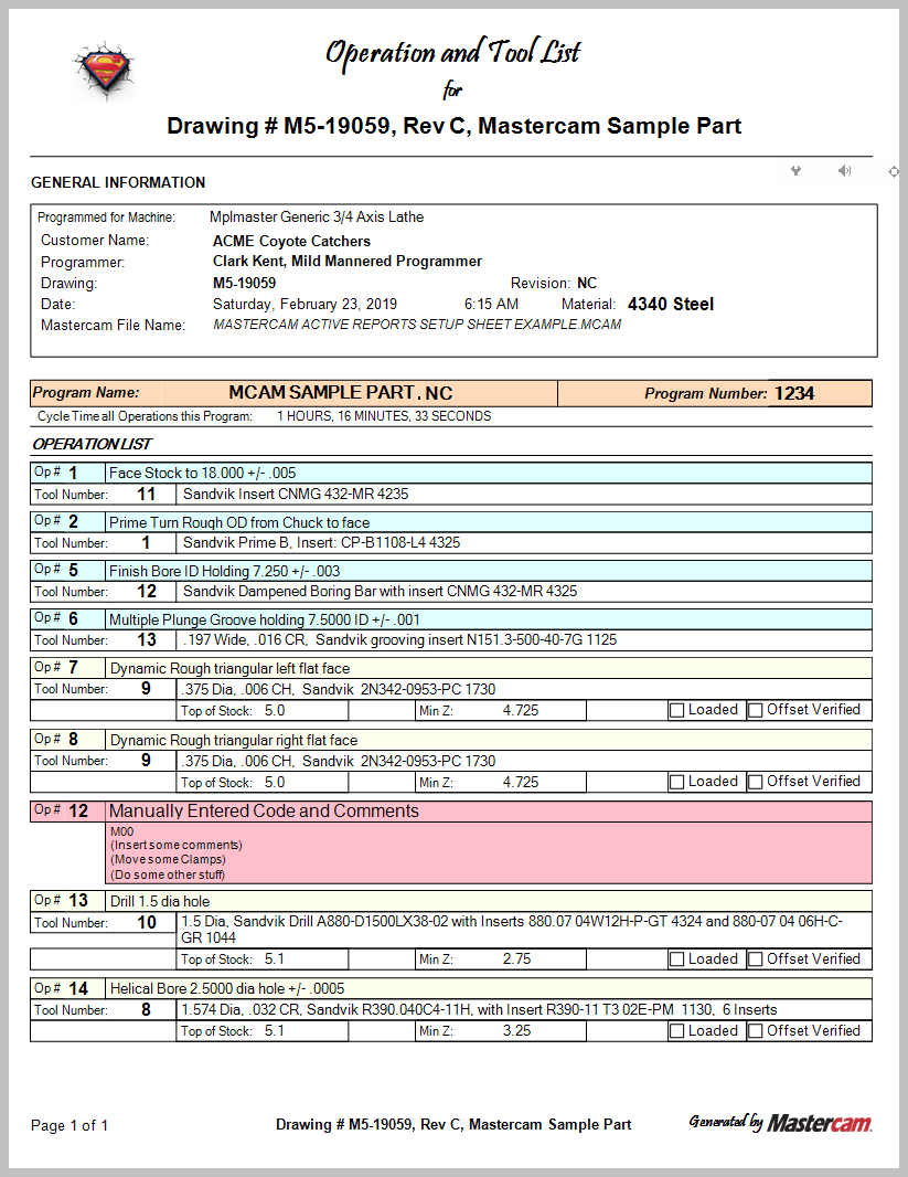
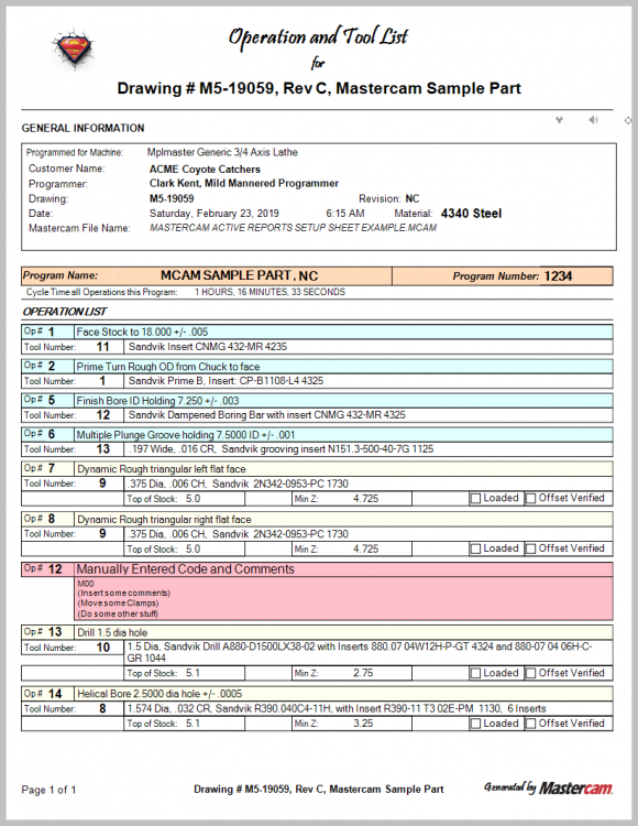
Greetings all, I have developed a setup sheet that is really more of an Operation check list. Developed for minimal paper waste. It works with all three of the main program types without changing report templates: Mill, Lathe, and Mill/Turn. The operations are color coded: Blue is turning, Yellow is Milling, and red is Manual Entry. If the tools are named in Mastercam the way that I recommend, all of the information will be there for the operator: Insert codes, etc. Included in the zip file that is attached is a sample turning program with milling, the Active report templates, a Word doc with instructions on how to install and where to enter information. For best results, pay close attention to the Word doc on what and where I enter the names and comments of the tools and operations. Disclaimer: Use at your own risk. Active_Reports_OP_Tool_List_short.zip
 12 points
 -
In-House Solutions is excited to release all of our Mastercam 2023 training material free of charge. You are free to download the pdf training material and Part files but check back often as we do update this material regularly. This is the same training material we use in our training classes you just don’t get the expert trainer to walking you through it. https://www.inhousesolutions.com/resource/mastercam-2023-training-links/?fbclid=IwAR37BKhkMZ2SFG6_3x2l54fH-hdj9hCVQti4mQtgs0mPhoYu_uPEH1h_SYc11 points
-
Shameless plug Ron week on CamInstructor. You can always call me. I liked working with you in the past and would be glad to help you when I have time.11 points
-
Sorry about the delay, I just now got a chance to play with it. Here's a video showing how I did it: I feel like I should put a Like and Subscribe and a Patreon plug in there11 points
-
Was doing some documentation and parameter stuff today and figured I'd share. FANUC gets a bad rap for a number of reasons, many reasons are self inflicted, however that doesn't take away from the power that is available on machines with Custom MACRO B. Nearly everyone knows G10 (FANUC's key to write to tool offsets, work offsets, parameters, etc...). It's not the only way though; Another way to write/access work offsets; Common(EXT) [#_WZCMN[1]]=-10.1234 (WRITES -10.1234 TO THE COMMON WORK OFFSET FOR X) [#_WZCMN[2]]=-8.7654 (WRITES -8.7654 TO THE COMMON WORK OFFSET FOR Y) [#_WZCMN[3]]=-16.5432 (WRITES -16.5432 TO THE COMMON WORK OFFSET FOR Z) [#_WZCMN[4]]=-1.234 (WRITES -1.234 TO THE COMMON WORK OFFSET FOR THE 4TH AXIS) [#_WZCMN[5]]=54.321 (WRITES 54.321 TO THE COMMON WORK OFFSET FOR THE 5TH AXIS) G54 [#_WZG54[1]]=-10.1234 (WRITES -10.1234 TO G54 FOR X) [#_WZG54[2]]=-8.7654 (WRITES -8.7654 TO G54 FOR Y) [#_WZG54[3]]=-16.5432 (WRITES -16.5432 TO G54 FOR Z) [#_WZG54[4]]=-1.234 (WRITES -1.234 TO G54 FOR THE 4TH AXIS) [#_WZG54[5]]=54.321 (WRITES 54.321 TO G54 FOR THE 5TH AXIS) G55 [#_WZG55[1]]=-10.1234 (WRITES -10.1234 TO G55 FOR X) [#_WZG55[2]]=-8.7654 (WRITES -8.7654 TO G55 FOR Y) [#_WZG55[3]]=-16.5432 (WRITES -16.5432 TO G55 FOR Z) [#_WZG55[4]]=-1.234 (WRITES -1.234 TO G55 FOR THE 4TH AXIS) [#_WZG55[5]]=54.321 (WRITES 54.321 TO G55 FOR THE 5TH AXIS) G54.1P1 [#_WZP1[1]]=-10.1234 (WRITES -10.1234 TO G54.1 P1 FOR X) [#_WZP1[2]]=-8.7654 (WRITES -8.7654 TO G54.1 P1 FOR Y) [#_WZP1[3]]=-16.5432 (WRITES -16.5432 TO G54.1 P1 FOR Z) [#_WZP1[4]]=-1.234 (WRITES -1.234 TO G54.1 P1 FOR THE 4TH AXIS) [#_WZP1[5]]=54.321 (WRITES 54.321 TO G54.1 P1 FOR THE 5TH AXIS) Tool offset registers (Memory C by var. name – D-Comp – Param. #5004.2=1): These registers may be read from and or written to. H-GEO H-WEAR D-GEO D-WEAR T1 [#_OFSHG[1]] [#_OFSHW[1]] [#_OFSDG[1]] [#_OFSDW[1]] T2 [#_OFSHG[2]] [#_OFSHW[2]] [#_OFSDG[2]] [#_OFSDW[2]] T998 [#_OFSHG[998]] [#_OFSHW[998]] [#_OFSDG[998]] [#_OFSDW[998]] Tool offset registers (Memory C by var. name – R-Comp – Param. #5004.2=0): These registers may be read from and or written to. H-GEO H-WEAR R-GEO R-WEAR T1 [#_OFSHG[1]] [#_OFSHW[1]] [#_OFSRG[1]] [#_OFSRW[1]] T2 [#_OFSHG[2]] [#_OFSHW[2]] [#_OFSRG[2]] [#_OFSRW[2]] T998 [#_OFSHG[998]] [#_OFSHW[998]] [#_OFSRG[998]] [#_OFSRW[998]] Pretty much everything has a name. In the FANUC Series 30i-MODEL B Common to Lathe System/Machining Center System OPERATOR'S MANUAL B-64484EN_03 they can be found in the Custom Macro section. HTH11 points
-
All a college degree proves is that you are capable of learning. It is experience at the school of hard knocks that makes you valuable to an employer11 points
-
So week 1 has come and gone and spindle hours were up 15% from the last week in July where we were at normal operating conditions.11 points
-
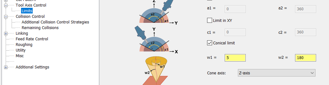
Hey Everyone, I've been answering some 5-Axis Programming questions for one of our members by email, which is a terrible method of conducting training. I've decided to try a new feature on YouTube, and I'll be hosting a "YouTube Live" event this coming Saturday, starting at 2:00 PM Eastern Time. I think we'll likely go for about 2 hours, and I'll be covering some very basic 5-Axis toolpaths. I'll mostly be focusing on Curve 5X, and how to do some basic geometry creation (Tool Axis Control Lines), for 5-Axis Trimming. This is my first time using YouTube Live, so I'm not sure if I can schedule an event (like you would for a Webinar). I will post a link to the Webinar in this thread, about 10-15 minutes before the start of the Live session on Saturday. For anyone who can't make it, I will be hosting the video recording of the session on my YouTube Channel. (See link in my signature.)11 points
-
You can easily start a fire which burns through the bottom of your machine, and continues burning through the concrete, until all the magnesium is consumed in the fire. Fire suppression is a good hedge against risk, but fire prevention is much more important. A Class "D" extinguisher may save the fire from spreading to your entire shop, but it may not save the machine. I worked at a shop which occasionally would build parts from large magnesium casting. These are machined on open-bed Deckel CNC machines (before the merger), and the orders were to "sweep up all the chips/swarf after each and every cut, and transfer the chips to the chip barrel outside, at the far end of the parking lot". Letting the magnesium chips build up and/or moving on to other operations/work before cleaning up the fire hazard, was a terminable offense. When I was young, I thought this was overkill. With the benefit of experience comes wisdom, and now I completely understand and agree with the need for these rules!10 points
-
Yes very serious offer. How I feed my family and keep a roof over my head. i was in Oregon a couple weeks ago supporting a customer. I helped reduce a run time on a proven part from 5-1/2 hour to 2 hours. They are running 40 parts a month for the next 3 years. They have gained 5 hours per part 2-1/2 per part savings and 2-1/2 hour to use on other parts. 40 hours of my time resulted in 2400 hours a year in savings for that customer. I am working on a mill/Turn part where i think we will see the same kind of savings. Two parts that saved a customer over 4000 hours proves I might know one or two things about manufacturing. Not perfect and not the best, but I have 35+ years experience so that does help. I have been to 46 states, 30 countries and 4 continents in my travels.10 points
-
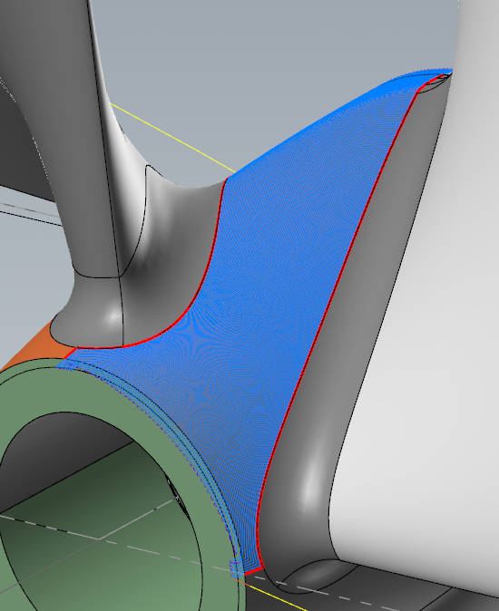
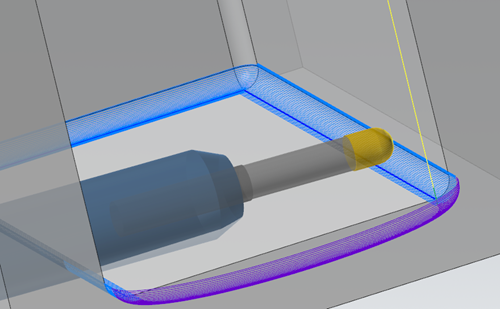
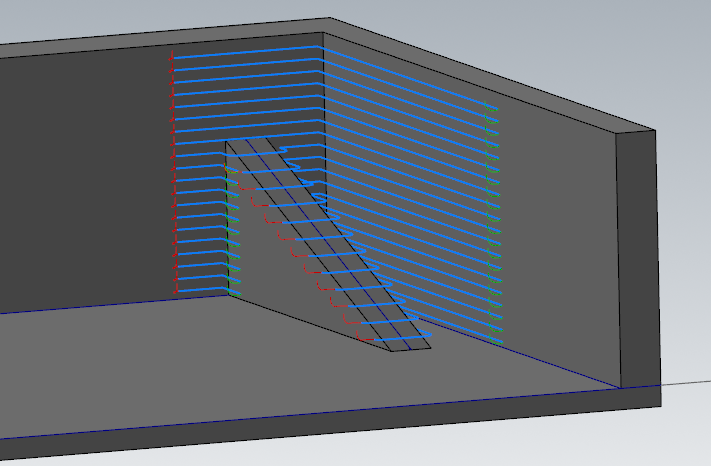
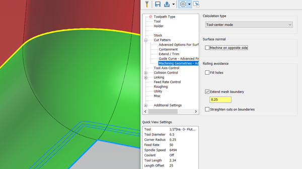
Tl;dr - Cut Pattern > Style to Guide instead of Parallel, or, Advanced Options for Surface Quality > Method > Exact instead of Approximate. ---------------------------- The reason for this is the collapse of the pattern due to your tool axis control. If you turn off collision control and set the Tool Axis Control back to "surface", here's what the "raw" Parallel toolpath looks like: When you turn on Tool Axis Control set to Fixed Angle to Axis (good call, BTW), it keeps all of these passes, but it's now trying to keep the same surface contact point with the new tool position. Since the toolpath is set to Center/Tip, it looks worse than it would if you could see the contact point, but that's still a really fine stepover for a fillet at the bottom. The changes I would make: Change the pattern type to (2) Guides instead of Parallel. That'll let the toolpath blend between the top and bottom better and you can benefit from Machining Geometry > Calculation Type > Tool-Center Mode (the default), where it's smart enough to calculate it based on the tool center. It gets rid of the gouging/fishtailing you have on the corner as well. When your fillet is almost the same size as the tool like it is in this case, I'd recommend tightening up the Cut Tolerance, maybe .0001 instead of the default .001? I'd also change your Collision Control to tilt to avoid the walls unless you have a specific reason to ask it to retract if it gets close to the wall? I think you'd prefer to have it tilt away. You probably don't need to use the second collision control.
 10 points
 -
Make sure everyone in the department uses the same posts. There's multiple ways to handle that and which way works best depends on your IT Infrastructure. Create a method for setup guys to put program change orders in.. amd when practical MAKE THE CHANGES. This way setup guys feel some ownership in the process and heads off the need for han-edits at the machine. Figure out each guy's strengths and weaknesses. If you can, 80% of the time give them projects that will challenge them and 20% of the time give them something they can crush. Work from common tool libraries and use common workholding whenever/wherever possible. Make sure you've got your holders in the tool library too. Reward excellence, not only programmers that put out quality programs, but that try new things AND SHARE with their peers. There's no room for the guys that keep stuff to themselves anymore. Those days are gone. We can't keep hurting ourselves because some guy's fragile ego can't handle competition. Just a few thoughts off the top of my head.10 points
-
We have just posted our updated 2024 training material on our website. See this link to download https://www.inhousesolutions.com/resource/mastercam-2024-training-links/10 points
-
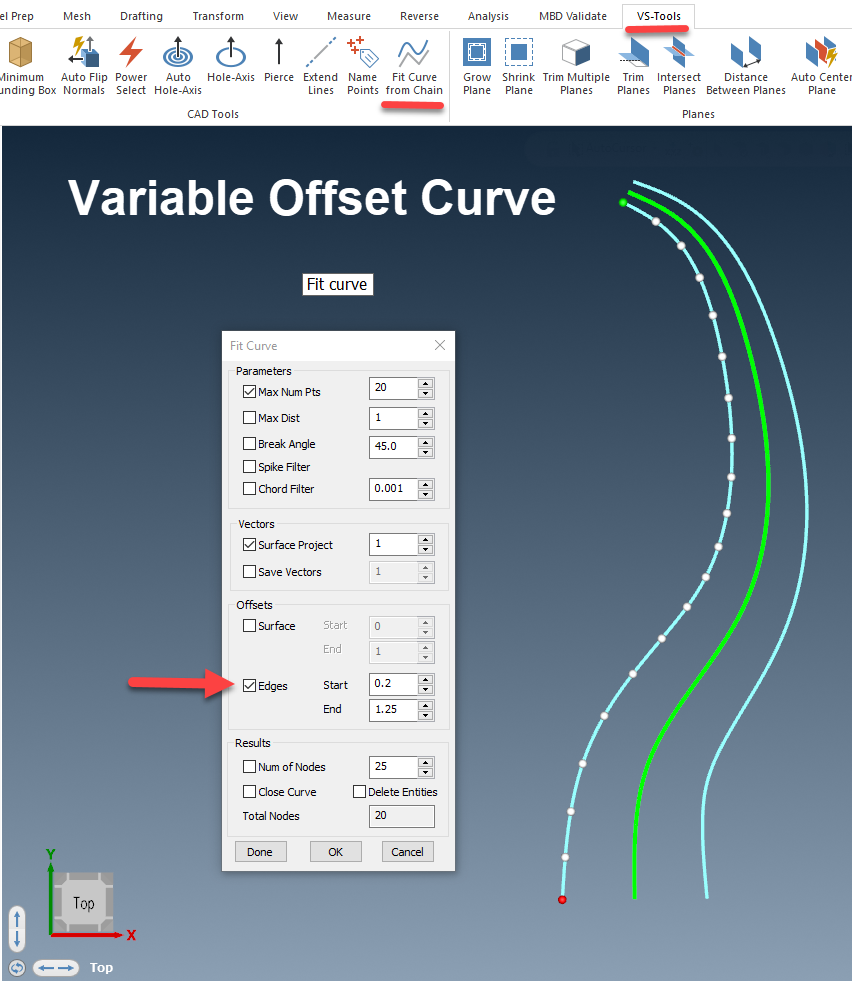
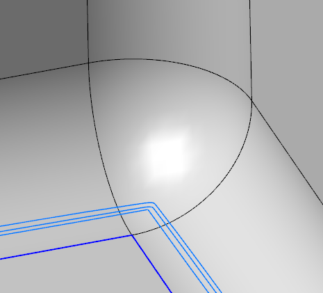
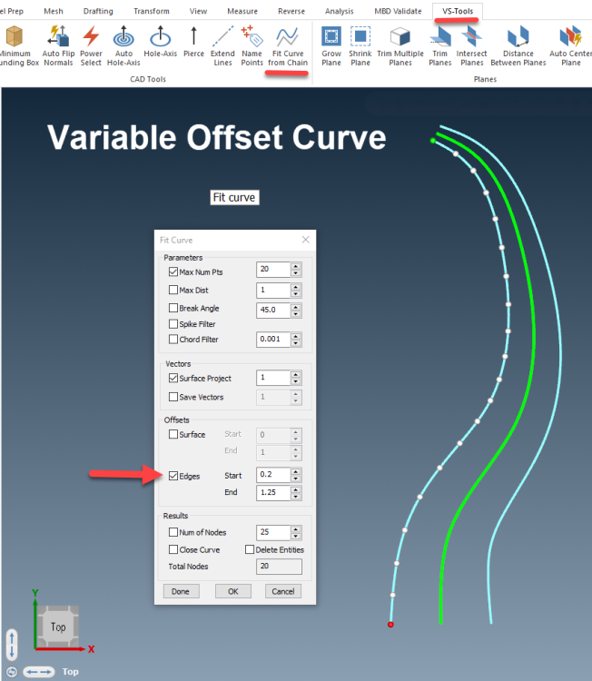
Variable Offset Curve or Spline Here is a simple way to create a variable offset curve in Mastercam. Simply use the Free Tools for Mastercam from Verisurf. https://www.verisurf.com/verisurf-tools-for-mastercam Chain a curve or spline and set the number of points and edge offsets of the start and end, you will get a new variable offset curve to use for your design.
 10 points
 -
I really don't understand why CNC Software would release Machine Group Setup, in its current form. - You can "setup your machine simulation", but not really. Because the MGS selections, don't actually "do anything". You still have to use the "Machine Simulation Setup", so I just see a bunch of "extra stuff for the future", with no practical application in 2023. But even worse, things that "used to work in Machine Group Properties", now no longer work in Machine Group Setup. - You can select "material", but that doesn't actually select material for your Speed/Feed calculations. You must go to the "Material button" on the ribbon bar. You actually "set the material" under the Master Model menu, but it is only "displayed" under the Stock Setup. Why wouldn't they just use the same controls on each panel, so you could see & edit the material type and properties, in both places? - Stock Setup > they got rid of '2-points', and you now must go through the 'Bounding Box' button, to create rectangular or cylindrical stock. But the interface for Bounding Box doesn't really make it clear that you can just "type in stock values", as the first control you are presented with is "manual geometry selection" or "automatic". How is this not completely worse than the old method User Interface for Machine Group Properties? There is the "Machine Setup", which is the files you are programming with (MD/CD/PST), oh, and they stuck the Line (Sequence Numbering), Program Number, and Comment Output Checkboxes, with the MD, CD, PST Files? If it were me, I would make the following changes to the layout of the Machine Group Setup: Page 1 would be Machine Setup > MD/CD/PST, and Machine Simulation drop-downs/selection, and configuration options (move other settings below) Page 2 would be Model Setup > which would include 'Master Model' (Part) section, 'Stock' section, and 'Workholding' section. Material could be assigned/viewed/edited with a 'common control' on both Part and Stock pages. (Keep the 'Master Model' term if you like it, but I think Siemens may have a legitimate grip with using that term, although I don't know if they have it copyrighted, they've been using that term for a long time in their training materials...) Page 3 would be Program & Tool Settings > (Basically, take the "Tools" page, and add some controls, and move some settings from other pages. For example, move Tool & Operation Library selection to this page, also Program Comment Control, Sequence Numbers, and Program Number settings, I would eventually love to see "Control Settings" available on the "Program & Tool Settings" panel, because then all "program output and formatting controls" would be accessible through the MGS panels, rather than having to use the Machine Definition Manager, and Control Definition Manager functions, in a separate part of the software. It would also be cool if there was an option for "material", where we could have a "HUD" (Head's Up Display) checkbox, where that data would display overlayed on the screen, while manipulating the Bounding Box function. It would be cool if you could edit or push/pull the stock size, and based on the HUD being enabled, and material assigned, and see the results of those changes in the HUD data being overlaid on the screen. Vericut has the HUD function for displaying your NC Program, while running, and I love that feature. I think honestly, the only change I really like, is the ability to set a different 'Stock Color' on the Stock Setup page.10 points
-
We actually send very little information to the operators. No comments, no tool information. Most things are checked by the machine... We have multiple tool databases (Mastercam, Vericut, etc...) but our Vericut database is king, meaning if there is ever a question about a tool's geometry Vericut is the record of reference. This is because we have a policy of 100% of our programs passing Vericut before going to the machines so if a tool is constructed to the Vericut spec it is safe to run. We have a software application in our tool crib where the tech enters the tool number and it pulls the tool information from Vericut and displays it on the computer. This includes cutter information, holder information, stickout, and min OAL plus a graphic of what it looks like. The tools are stored in a locked cabinet (Western Tool's FTS system, it is a 10!). When the tool manager needs a cutter he types in the tool number and it tells him the location of the tool by cabinet, drawer, row, and column. We set our tools using a Speroni presetter and the values are entered into our cell controller which will not accept a tool that is out of spec to its definition in the cell controller. The minimum length of the tool definition is equal to the length of the tool in the Vericut library. When the tool is loaded into the machine it triggers a first use macro, so the machine measures the tool with the laser the first time it goes into the spindle. If the tool is out more than .01" it is flagged as broken and prevented from further use. We have one tool library in our shop and that covers turning and milling, CAT40, CAPTO C6, C4, etc... We aren't a huge shop so it isn't an issue yet. These are all SOPs in our shop and they are written into our quality manual for AS9100. The main driver behind most of the processes is the lack of skilled labor in this field and also the fact that even skilled labor folks have bad days and can $hit the bed with the best of them, myself included. Qualified machinists seem to be a dying breed and some of the folks I have seem present themselves as a 'machinist' were really disappointing. Our toolroom manager started with zero machining experience and he started running the toolroom after about three months on the job. This is because he is VERY good at the details but the machines still check his work. Most of our machinists started with zero to less than two years experience and that includes our entire metrology department. The processes are all designed with that in mind. With this system we haven't had a tooling issue in a few years and yes, I'm knocking on my desk right now. I'm not sure this answers the question given above but I figured I'd share our processes on how we handle tooling. We have similar processes for every other aspect of the shop (first article, program prove out, program control, etc...) and they are followed to the letter and thus they work well.10 points
-
When doing dynamic paths and I anticipate slivers that will be problematic. Typically I'll do what @crazy^millman does mostly... i figure out where the problem areas will be with verify,, create a boundary,, then return to that area with a ramping toolpath. Only took grenading a 1" solid carbide endmill to learn that lesson. I call those tuition payments. A statement I stole from Pete Roberts CEO of Origin Maine when he spoke of mistakes made in business calling them tuition payments. These situations are not unique to Mastercam contrary to popular belief. Part topology, approach, stepover, etc... all play a part in the Ultimate outcome and success.10 points
-
There is this series with Ron (He is always on this forum helping us!!). Thanks Ron! Then there is Colin (also on here helping us!!!). Thanks Colin!10 points
-
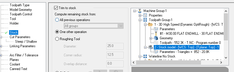
Remember, with Waterline (and all HST toolpaths, and multiaxis toolpaths, and...), you can use Stock. For example, let's say that you waterline the whole inside and get this: If you had a stock model that had the roughed out part: In the toolpaths, go like this: The results will be this: Obviously, this is a poorly done example, but I think that it might make your life easier.. Waterline Stock.zip
 10 points
 -
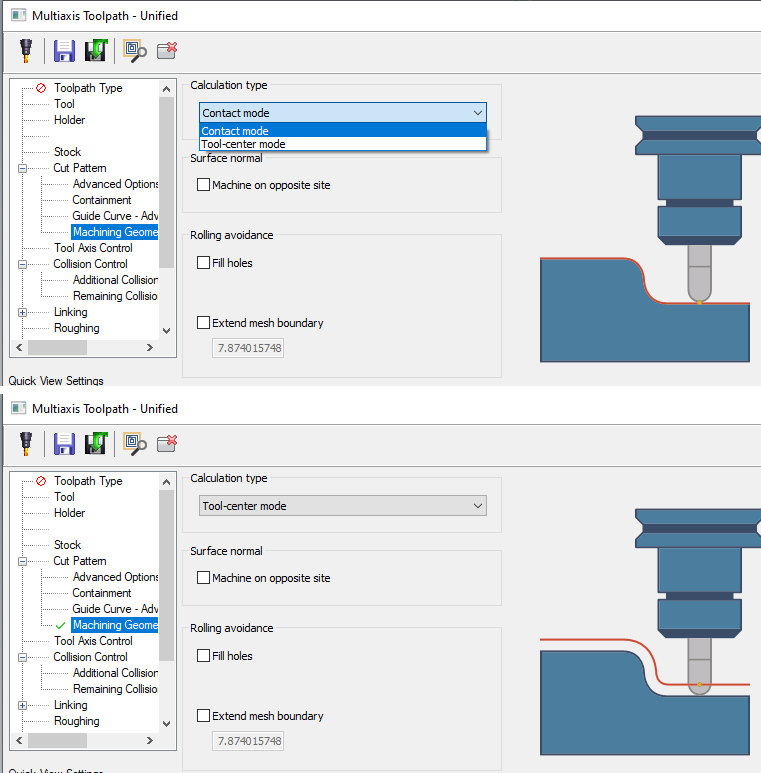
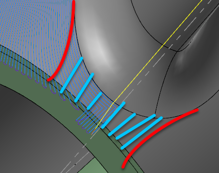
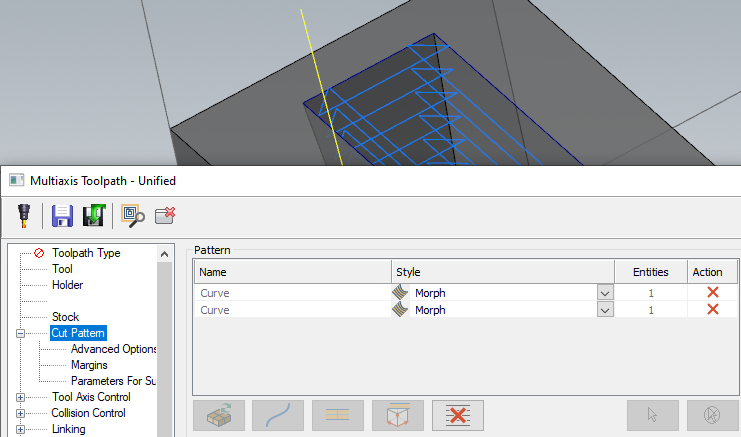
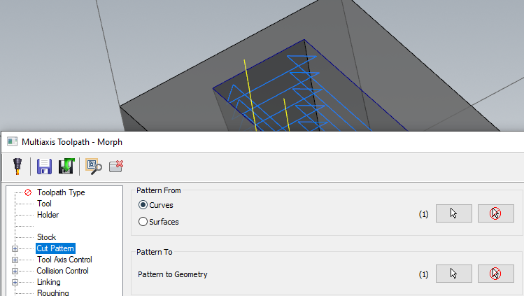
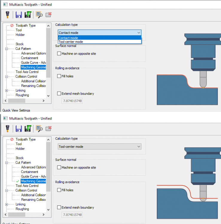
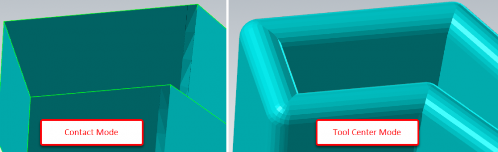
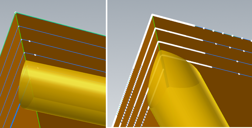
A couple of notes: If you've got Unified set to "Morph," it's the same exact algorithm that the Morph toolpath uses: vs (Images above with no collision detection/corner smoothing). In your case, you're using "Automatic - Morph" which is a completely different algorithm, so it's the same sort of problem, but it manifests itself differently. The older surface-based morph is a bit easier to understand, so let's take a look at why it does what it does (again, no trimming or corner detection): You can see that it's trying to make sure it cuts every little bit available, so it will run the quadrant of the tool right to the edge of the surface. It has "no knowledge" of the other surface at that moment, and relies on Collision Control to deal with it, or a corner smoothing post-process to analyze the resultant toolpath and trim it back to fit rounded corners. The Geodesic method is a a completely different beast. It's going to mesh the entire set of geometry and generate the toolpath on that. It actually has two modes as you've discovered, Tool Contact and Tool-Center mode (pay close attention to the picture, for each, it's important): Tool Contact mode is like making a stock model of your surfaces. Tool-Center is like making a stock model with an additional offset of the radius of the tool (which is why it only works with full radius tools such as Ball & Lollipop): All that is to say, it's the same basic problem as the surface based version, but it manifests kinda different. With both versions of the toolpath, it runs through the magical black box that calculates the raw passes (and that's what's different), and the raw passes are generated from the center-tip. Since the surface based version (old school Morph) is looking at individual surfaces, whereas the Geodesic (Automatic/Guide modes in Unified) will calculate a full mesh, which means that it "understands" that the corners exist: (both toolpaths set to Tool Axis Control > Surface with no collision detection) Look at how much denser the vectors are with the same tolerance Surface vs. Geodesic based! That's because the Geo. recognizes that it will have to "roll" through the corner, and the old surface doesn't, it just runs to the end and then will snap to the next surface. So, now that the Raw Passes are generated, now it applies the Tool Axis Control, which is just going to take all of the calculated points and tilt the tool, then compensate it outwards to maintain the tool contact point, which is why you get the old "Fishtail" with old style, and the weird looking comp thing with the new ones. As you know, you can trim it up some with either Round Corners or Collision Control set to Trim. One of the super-powers of the Geodesic version, though, is when you use a round tool like a Ball Mill.. Being able to calculate the corners properly means that you're going to generate a gouge-free toolpath from the get-go, no need to trim it up with collision or other tricks. Here's what that toolpath would look like if you just ran ball mill in Tool Center Mode instead of a flat: (View from approximately the top) Look at that beautiful contact calculation! Hope this helps your understanding!
 10 points
 -
I added all my common stock in the Geometry page on the HST so I don't have to keep changing or adding Stock amounts.
 10 points
 -
You'll be seeing a steady stream of these throughout the year- glad they're of use!10 points
-
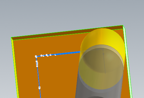
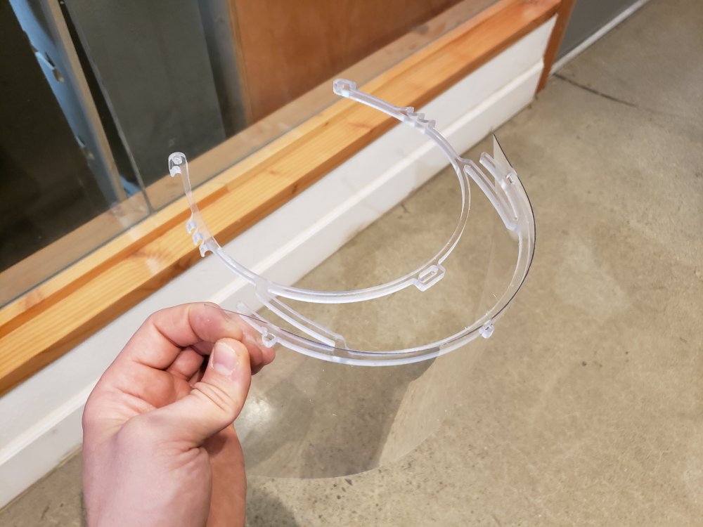
I've suddenly found that my normal work load has dropped off... Last week I started looking for ways that I could use the equipment and skills I have available to make Personal Protective Equipment for our Healthcare Professionals. I'd like to share a project I found and ask if anyone else has found other projects along these lines. I've adapted a 3d printing project to be cut on a CNC router. 2+ hours to 3d print, under 2 minutes to route. Grabcad files for routing: https://grabcad.com/library/covid19-face-shield-hole-punch-v1-1-1 Original Prusa 3d Printing Project: https://www.prusaprinters.org/prints/25857-protective-face-shield-rc1 I hope this is appropriate here, I wanted to reach people who may have the capability to make parts for their local communities, I feel that sharing on social media reaches a more diluted demographic...
 10 points
 -
They basically split up Trim/Break/Extend into separate functions. Where you used to be able to trim entities together, trim to a point, extend entities (positively or negatively) all from one dialogue box, you now need to accept and open up a new dialogue box for each function. I also dislike how they change "Extend" to "Modify Length". You used to be able to enter a negative value to shorten the wireframe, now you must select either Lengthen or Shorten and are only allowed positive values in the box. A very good workflow that used to contain a lot of functionality has, in my opinion, been completely neutered.10 points
-
I know one company just laid off 10% of their work force and the remaining programmers just had to pick up the load for a 50% reduction in their programming department. I think their ratio is 10 machines to 1 programmer now. I know of other places where it is 2 machines to 1 programmer. We have a new customer that had 1 to 1 and then they went to 15 to 1 in 2 months when a lot of the programmers left. The brush can be painted so broad that its hard to really say. Verification in what sense? Full CAV package with screen shots of every tool run through the CAV? Or just verify it through Mastercam and call it a day? What do the setup sheets require? We have one customer that if I were to run the program in my shop (if I had one) it would be 40 operations in Mastercam, but for them it becomes 500 operations all named, labeled and detailed out. Complete Tool Lists with EDP, Holders, and built in Mastercam ready to give a tool crib person to build without ever needing to think or do anything but build what you have given them. Can it be a Cat 50 Shrink it with 3/4 5 Flute Carbide endmill 1-1/2 LOC for Ti and that is good enough? Does it require probing? Are these billet, forgings and/or casting? Additive Parts? Printed? Sintered? Weldments? Heat Treatment of part as part of the process? Any Micro finishing? Pressure Testing? Lapping? Grinding? .000 True Positions regardless of feature size on 60" parts out of 7075-T8? I and 2 other programmer spent 1600 hours programming one part that runs for 800 hours. Took the roughing that previously on a similar part was a 100 hours and reduced it to 40. That was not good enough and and the company tried for 18 months to get it down to 10 hours with several different shops and finally settled on the fact that 180 cubic inches a minutes was good enough. Would it be that kind of place that think they can break the laws of physics? Just got project rejected a couple months ago we bid on that I was told my times were to far off to machine the part. When someone figures out how to machine Inconel with Carbide at 2000 sfm or Ti at 1500 sfm with one tool for 120 hours at a time I want to shake their hand. If it is one of those places then one programmer is probably to many people for that company. They are probably the company hearing that someone can use a certain software and after 3 days they can program any machine on the planet and cut any part. That same software is saying people who have spent 5,10,15,20,25,30 or more years learning and stilling learning how to do it are not needed anymore. It that a broad enough brush?10 points
-
If you have the "Auto-cursor" options enabled, you can press the letter of the keyboard shortcut for the "Auto Cursor Override" options. This means to snap to an Arc Center, you press the letter "C" on the keyboard. "M" for Midpoint, "E" for Endpoint, "O" for Origin, "I" for Intersection, "P" for Point, and so on. There is a lot of time to be gained from using these shortcuts.10 points
-
This is like saying you "just want to load up the pallet pool with material, and take a nap". Can it be done, absolutely! But there is no getting around all the investment in time and labor required to get to the point where you can just "print money". There is no cheap/free lunch in manufacturing. Metal Powder is expensive. So is the engineering required to get from idea to printed part, let alone all the way through "finished and delivered part to the customer". What competitive advantage can you apply, consistently, to make the 3D Printing process profitable in metal or plastic? I have yet to see a "job shop" enter the world of 3D printing (especially metal), and be instantaneously successful. You've got to find customers who are willing to pay for a technology to produce parts which "can't be made through traditional manufacturing technologies" (think engineered geometry like 'ntopology'), where the goal is to create periodic repeating geometric structures, for either "light weighting" purposes (lattice or generative design), or to find more efficient methods of heat transfer (like gyroid or diamond TMPS - triply periodic minimal surface). Most of the 3D Printed Metal Parts I've seen still require some sort of post-process step. Heat Treating or hot isostatic pressing (HIP) treatments help change the density and porosity characteristics of the part. Many 3D printed metal parts still require traditional post-process machining steps (flanges, O-ring grooves, bores, seals, ports, etc.) to make a finished component, ready to be installed on a product or assembly. One of the biggest hurdles to overcome are the materials and testing standards, and inspection processes, to qualify parts for any process which is safety critical. Phillips has sold additive machines since 2000, and distributes for Markforged, EOS, and AML3D. We also build our own Phillips Hybrid machine, by integrating Meltio DED Print Heads onto Haas machines. These print heads feed a commercial welding wire down through the center of the nozzle, and hit the wire with 6 lasers (1,200 watts, 200 each) to form the melt pool. Our machines are an affordable entry point for additive, both new build and component repair processes, but you still need to make the business case for parts to be printed (to make the raw pre-form), and then finished machined. We also sell a standalone Meltio M450 machine, which only prints, but this way you and have one machine printing, while the CNC just handles the machining duties. If you'd like to talk one-on-one, I can share more information and details which I wouldn't want to publicly disclose. For example, Phillips is building and running the Additive Manufacturing Center of Excellence for the US Navy, in Danville VA, for 3D printing additive parts for the Columbia-class Submarine. https://www.linkedin.com/posts/fastechengineering_usnavy-dod-usmanufacturing-activity-7118217521836486658-mO7H?9 points
-
about 45, 27 HMC's, 10 VMC's, 5 MIll-Turns, 3-5AX's plus additive machine,. plus mold shop and tool room programming support We're a crew of 39 points
-
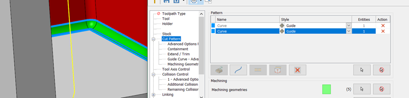
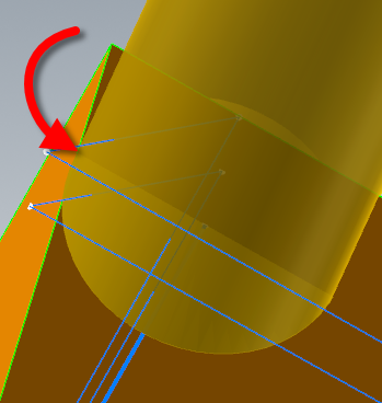
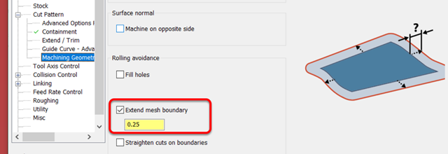
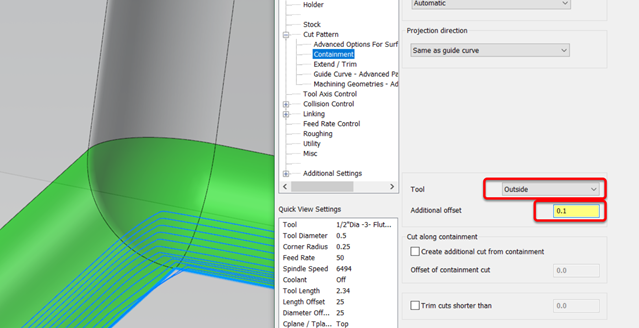
Ah, sorry, I missed that the side extension was essential. It's definitely not as easy as the surface-based toolpaths to do it with the geodesic engine, and you don't have a Top/Bottom extension, you can only do a blanket extension. It's not too hard, but you need a bit of background knowledge to really leverage it. Skip the next paragraph if you don't care about the mechanics of it One important note is that I'd recommend using this with a single Guide chain (Parallel equivalent), as having two that it's trying to Morph between can get a little weird sometimes. Geodesic engines are based on the mesh (they create a mesh in the background from your selected surfaces at whatever tolerance you specify). The edges of the mesh are considered a constraint that it has to stay within, using whatever pattern you wanted it to fit. So, you have two problems to solve: * One is that your mesh (the fillet) doesn't extend at all * Two is that your containment is based on the original mesh. To solve the first problem, use Cut parameters > Machining Geometry Advanced Params > Extend Mesh: You can preview the toolpath, but nothing will change at this point (other than taking longer to generate!): But, in the background, the mesh has been extended on all sides. So, to solve Problem Two, can be solved using Cut Pattern > Containment, and allowing the tool to go outside the containment: Other than that, I think you'd probably have to create the geometry you want to.
 9 points
 -
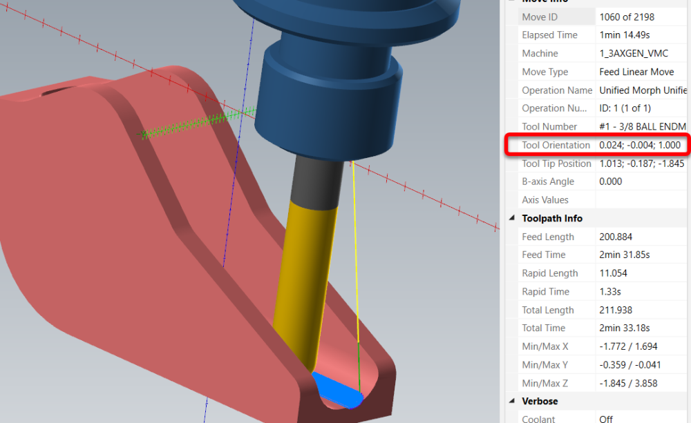
It's a problem that only exists when you post this.. It's called "singularity" when the spindle is perpendicular to the C axis. Basically, because the BC is near 0, it calculates that from one side of the B axis to other it decides that it needs to rotate the C axis nearly 180°. Most likely the transition before/after this move where it crosses B0C0: There's a couple of strategies you can use to solve this, but the easiest way is to simply not let it get vertical. If you limit the toolpath so it isn't allowed to go within, say, 5° of B0C0, you can just avoid the problem. On the tool axis control page, turn on "Limits", then do something like this:
 9 points
 -
Orrrrrrrrrrr FANUC Parameter #1401.1 =1 No dogleg rapid (LRP) if it's a FANUC 16, 18, 21, 30, 31, 32, or 0i...9 points
-
There was a question on the Official mastercam forums about how to get depths correct when slot milling with a woodruff or t-slot cutter type of tool and since the question comes up so often it seems with newer mastercam users i went ahead and made a calculator in excel to make the process easier for new users. if anyone would like to use the excel calculator its attached, i also have a video below on how it was intended to be used and from some quick testing it seems to work well. I typically do this math in my head whenever needed but i fully understand how mastercam calculates depth cuts and step downs so its easy for me and may not be for others which is the only reason i created this, in the past i have always just did this math myself whenever i need to but hopefully for others that may not have the same amount of depth cut calculation understanding this will give them a quick easy way to get all the math figured out. And good news anyways is CNC software has an enhancement request in for this to be even easier in the future, so some day this type of math may be not needed at all hopefully. video on the way the calculator was intended to be used https://fastechincorporated-my.sharepoint.com/:v:/g/personal/support_fastechinc_net/ERslKtcWv-ZOnkzxEEdMSJ8B75REvXSzM5c3RJTKNORx6A?e=heU8Zh slotting mcam calc.xlsx9 points
-
I was telling you! Sorry if I didn't quote you and make that clear. I see that you reached out on LinkedIn as well, and responded to your message. Helping people learn new skills and advance their careers is one of my favorite things to do in life. Early in my career I had mentors/sponsors who took the time to teach me new skills, and helped me to get where I'm at today, and it is my duty to pay it forward.9 points
-
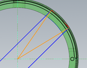
A handy way to check whether it's possible to do things is to look at it from the front, switch to 2d mode, create curves on edges (your straight walls) and modify length to see if they intersect the origin. Obviously, on this part it's easy to visually see that it's not gonna happen, but I've seen parts where the wall was only off .5° or so, so it looked like it was possible until you really analyzed it: What Ron's saying, in this example, you have to treat anything between the orange and blue as an undercut feature, as if you were doing an undercut wall on a 3 axis machine.
 9 points
 -
and if you are serious about it, you need a temperature controlled work space, temperature controlled coolant and you need to store your material in a temperature controlled environment. you also need a rigorous tool life management system worn inserts may still have some useable life to them, but at some point they are inducing heat into your work. Data like this can only be learned by trial and error though.9 points
-
I have 24 years of muscle memory for using Mastercam; I've been using it by keystroke since '94. The changes I had to make for the X series were trivial by comparison to what I'd have to do for 20XX. If I have to relearn from scratch I may as well learn another product, which I am seriously considering for when X9 gets too old. When a UI is not possible to use quickly and efficiently without heavy customization someone has made some very bad decisions. Furthermore, when it is not possible to customize a UI to make it behave like a previous version, yup, more very bad decisions.9 points
-
Wow, Do you actually expect to get help from people with an attitude like that? Feel free to ask anyone at CNC if they consider me a fanboy, I can guarantee the answer would always be no. But even with that I can honestly say your thoughts on Mastercam are flawed. The lack of a dedicated radio button in every path to do some obscure function that you have multiple other ways to accomplish already is not a flaw. What you are trying to do is a simple task, you are just choosing to make it more difficult on yourself. Manual entry being the easiest. You complain that it would be bad if you forgot to add that though. Well that is all on you. This is a trade where attention to detail is key. You had two people offer to edit your post for you and yet you keep complaining about not having time. Seems to me you just want to complain and nothing will stop your temper tantrum unless you get exactly what you want before you want it. A poor craftsman blames the tools for his failures.9 points