


Leaderboard


Popular Content
Showing content with the highest reputation on 06/17/2019 in all areas
-
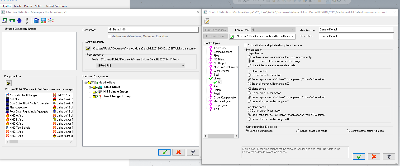
It may be the setting of verify. By default MasterCAM uses non-interpolated rapids (X and Y axis move at max.feed rate independently). This may give false crashes in tight spots. You have to change settings in the control definitions, (see image below) so that X and Y arrive at destination simultaneously. This may help.
 3 points
 -
I just re-generated 9 operations. One stock model and 8 Dynamic rough (rest machining) and watched the ram use in task manager. I saw it go as high as 88%. It took 45 seconds according to Mastercam logger regen these. I have 32 gb of ram and a 4gb video card. I use a windows add in to set Mastercam priority to high. I have no issues since doing this. The program is free. It is called PRIO. Google for it and install it. It has helped speed my times up and makes my system run more stable. You may have different results, but it seems to help my computer. Hopefully, it can help you guys also.2 points
-
In your config, the is a setting Toolpaths branch but there is nothing specific to stock models, toolpath crunching In reality, for what you're doing, 64 gigs should be minimum1 point
-
Now that you're at it... would you be so kind as to reprogram the whole operation tree and share it with us? I'd be forever grateful.1 point
-
What kind of machine? Are you seeing rotation collisions that won't really be there? If your simulation isn't tied to your post, simulation is "sketchy" at best, it misses things....one thing I have is my post gives me clearance moves automatically at rotation and offset changes for my HMC's...becasue I do this in the post, I get crashes that I know are not going to happen....what I am really using the simualtion for is checking clearances between holder, fixtures and parts.....I set my retract value to a large number and run simulation...once I know the clearances I am checking for are good, I set my clearance back to 1" and post. Not sure if you're seeing something similar. Review the collisions to see what's actually being reported.1 point
-
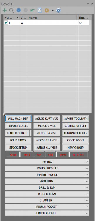
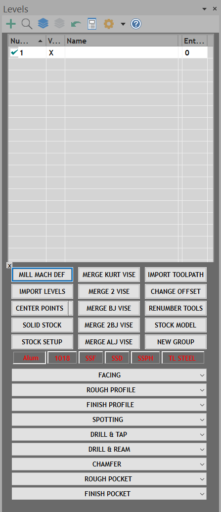
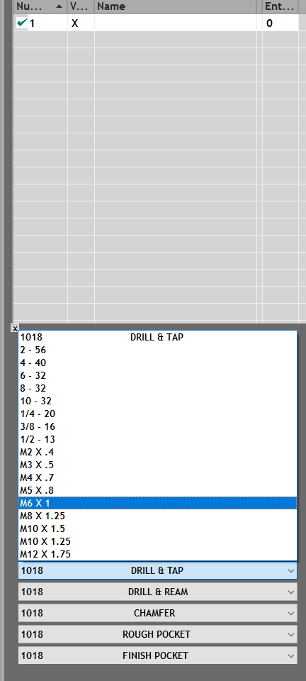
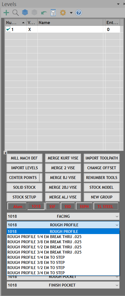
I have done exactly what Thad is saying with the ops libraries. But i got sick of going through the import process and searching for the correct toolpaths i needed to import even though i had them labeled good like Thad's examples. Once you get all the toolpaths for all the different scenarios it can get into the 500 - 1000 toolpaths if not more. So what i did was design and code a window that sits in the levels manager with buttons and drop-down menus to automatically import what i need. I also made it for different materials so i dont have to mess around with changing tools or speeds and feeds. I pick to material i want, pick the operations i need and BOOM its imported at the red arrow and i just pick geometry.....Done! I just click and in seconds what i need is imported. I also use same window for doing other common everyday tasks as you can see in the pictures. It took many hours of work and coding but i'm so glad i did it.

 1 point
 -
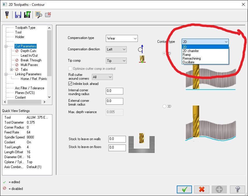
Another tip for the contour parameters...even though you may have separate ops saved for the various options (2D, remachine, ramp, etc) within contour, go into each option and set each type's parameters the way you like them, then disable the option. To clarify, say you have a plain old 2D contour op saved. What if, after you import it, you want to change it to contour-ramp? When you select ramp from the drop down, all of your settings for ramp should be set already. Same with remachine, etc. Every contour operation in your library should be saved so that you can change contour types and those parameters are already setup. Does that make sense. I'm not sure if I'm describing that clear.
 1 point
 -
I think a lot of it depends on the quality of machine. If you are talking a high end Japanese machine with high quality mechanical components and top notch servos for smooth motion, then you should be fine. If you are talking a cheap machine, those are not built to last regardless of how you use them.1 point
-
Since they are editable , I'm sure people will find this useful . Personally , I don't use them .... GRacjan1 point
-
This is a good suggestion, you can use the pocket path for facing: and then use the finishing tab: Use zigzag and under cut parameters, set wall to -(half of cutter + lead in/out).1 point
-
What I typically do is setup 2 separate operations to handle the roughing and finishing. In the first Operation, I disable Clearance and Retract, but first I change the options for both to "0.0" and "Incremental". I set the Feed Plane to 0.0 Incremental. I set the depth (typically), to how ever much stock I want to leave (say .040), and set it to Incremental. If I am doing several depth cuts, I set the Top of Stock to the correct value as Incremental from my depth. (Say .500 for example.) Then I set my Max Depth value. In this case we are starting at .500 above Z Zero with the stock, and leaving. 040, so we are removing 0.460 of stock. I'll set my max depth step value to .100. That means we take the total depth (.46), divided by the Max Step value (.100), and we get 4.6 as the answer. Mastercam uses the max depth as a limit. So when a division is made, and the number is not a whole number, the system round the value up to the nearest whole integer, and performs the calculation again. (0.46 ÷ 5 = .092 per pass) So Mastercam would rough each step as 5 depth cuts of .092 thick per pass. Or if we can push the tool deeper than .100, we simply divide the total depth by the actual number of passes we want. For example, 0.46 ÷ 4 = .115 per pass. So we set our max step to .115 and we get 4 depth passes. Now, in the Reference Points, we add an "Approach" point of Incremental (Z only) set to 2. Or 4. Inches. This gives us our initial approach point to start the cutting. Because we have the depths set to .04 Incremental and the Clearance and Retract disabled, the tool will not retract at the end of the Operation. We can then copy and paste the Operation. Disable Depth Cuts, set Depth to 0. (Same for TOS and Feed Plane). Adjust speeds and feeds. Now, disable the Approach Point, and add a Retract Point, for Z Incremental, at whatever hight you want. So, the first Operation uses Approach Point to get the Tool to the start. Then the Op roughs the material, leaving some on the floor for Finish. Important: the tool does not retract in the NCI Data. The 2nd Op has "no approach move", so the tool simply moves to the start point between Ops. The 2nd Op cuts the floor with finish parameters. (Often I will kick up the stepover from 65% for roughing, to 90% for finishing), and adjusted speed feed values. The 2nd Op uses a Retraction Reference Point to get the tool raised back up to a safe location.1 point
-
As a side note to this problem, I only have 16 gigs of RAM on my machine, but when I look at my Task Manager Performance tab on a heavy crunching operation, it only allows me to utilize 8-9gb of RAM. I have my Mastercam config set to use 80%...am I missing something?0 points


.thumb.jpg.d4de3779c381ac511dbaaf4f87d2ea0c.jpg)