Leaderboard


Popular Content
Showing content with the highest reputation on 08/07/2019 in all areas
-
<soapbox mode> Weelllllll, if you were to define the HMC logically instead of the "default" Mastercam way, there likely won't be any conversion needed for the 5 axis toolpaths. Now's a prime time to avoid starting a bad habit if they haven't had any previous HMC programs. The default way of handling HMC in Mastercam is to invert the Z axis (spindle) direction in the machine def, and the post then unrotates it during processing, which is why you have to program everything in the TOP/FRONT/FRONT. If you can't tell, I've been a long opponent of this way of programming, as to me it's completely illogical. The Z is spindle... Don't put in an artificial rotation! TOP/TOP/TOP should be the same on a VMC as an HMC! If you set up your machine just like a VMC, then you can post just like a VMC to ANY machine! </soapbox mode> Other than that, unfortunately, there's no quick way to edit the multiaxis toolpaths. Because the change meant than any reference to axis has been updated, you can have situations where you have to change from X to Z in Tool Axis Control, Collision Control, Cut Pattern, etc. And, because we were completely WCS un-aware prior to that, I was never able to figure out a fool-proof conversion so it didn't seem worth the risk to try to make global edits when we might not guess correctly.3 points
-
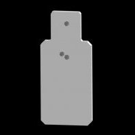
That is the 2D tpath on the left of your screen shot, Terry is looking specifically for a 3D surface tpath2 points
-
not sure if this is the issue but i created a pmesh from the last stock model in operation 1 then i created a stock model from that in the 2nd machine group then it seemed to work not too slowly the other thing is that you dont have to have 2 machine groups for this especially if it is the same machine
 1 point
 -
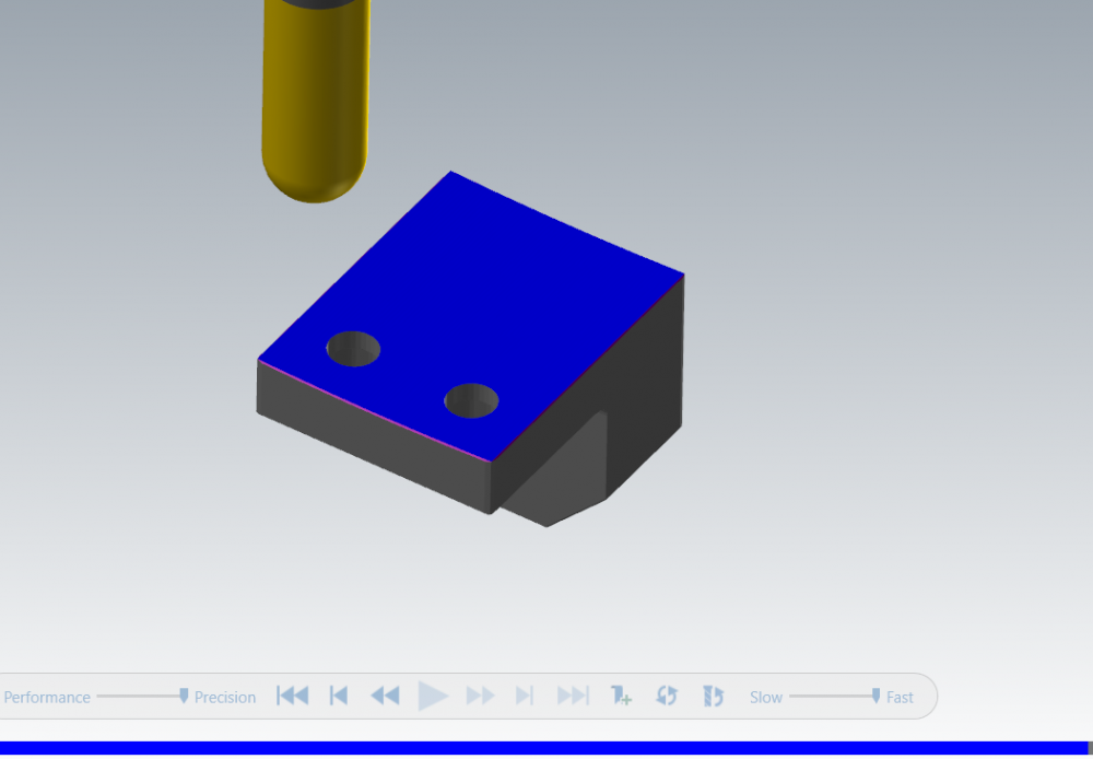
here are the files converted for you Lower_Guidingblock_deadsolid.stp Stainless pipe.dwg Upper guidingblock deadsolid.stp1 point
-
Hi Terry, The post is from an outside supplier that I'm not even familiar with. Its a suggestion I will make to our customer but as to whether their post people can/will do it is another matter....1 point
-
That section of the post is called before a toolchange and null toolchange....it wants to, as you've seen, send the B axis home, reset it's position to B0.. The last 2 variables cabs! cinc! That ! sign updates the rotary variable to it's current value but tells it to not output.....so the calculation for the next toolpath begins to calculate it's rotations move from 01 point
-
+1 My *feeling* is that it was changed because the hori boys then had automagic planes set-up that would output correctly (0,90,180,270) Doesn't make it right though... Rich - Phil helped me convert my VMC 4th axis post to a Hori and we did exactly as Aaron said - TOP/TOP/TOP. As your customer has this new machine, perhaps they should go this way too from the start?1 point
-
I think the 2019 HLE will still allow you to open an X6 file directly. So you could open it with that and export the nodel as a step.1 point
-
with all the bugs we have found in 2019, and all the work arounds we have to do to get our jobs done, not sure I want to even mess with 2020........used to really like MC now its a shot in the dark whats going to change on a daily basis and what will work this time and not the next.1 point
-
First problem I see is you have "0.0" for Arc Sweep. This is not allowing an Arc to be created, at all! Your Boundary is allowing the Tool to "roll" around the corner. Surface Finish Contour is funny like that sometimes. I would build a new Containment Boundary, and take the two lines that lie along the walls of your part, and extend them out straight, 2X or 3X the diameter of your cutter. Then trim those extended lines to a new vertical line. Then "uncheck" the "allow line/arc outside boundary" checkbox. This will force the entry/exit line/arcs to be fully contained inside the Containment Boundary. With Surface Finish Contour, in general, I always spend extra time to build a "good" Containment Boundary. It is often the CB itself that is instrumental in getting the Cut Motion of the tool to occur when you expect it to.1 point
-
Hi Dave, "non-X Style Coolant" (known colloquially as "V9 Style Coolant"), only allows you to have 3 coolant "On" Options, and a single "Off" option. Some Post Developers will "tweak" the V9 Style Coolant, to add separate "Off" codes, but they are still limited to only supporting 3 coolant options in the Mastercam Interface. If you are adamant about sticking with V9 Style Coolant, then you cannot access more than 3 coolant options. That's just the way the system is configured. -------------------- I know you don't want to use X-Style Coolant, due to the Before/With/After, but there is a work-around that might interest you. The Before/With/After options are designed to be output with the following Post Blocks: Before - The "Before" flagged codes are output through 'pcan' Post Block, as a Separate Line of Code. With - The "With" flagged codes are output in a 2-step process. 'pcan1' builds a string: 'strcantext'. The 'strcantext' output string, then outputs the M-codes. After - The "After" flagged codes are output through 'pcan2' Post Block, as a Separate Line of Code. If you don't use the "Canned Text" options (at all), and some people do not, then you have the option to simply move the 'pcan' Post Block Calls, so that the "Before" Coolant just comes out exactly where you want it to. That way you don't have to mess with changing all the default settings...1 point
-
Why is this Odd? This is exactly how I program when given a choice. I use 'Computer' for all Roughing passes. I'll never use Comp on a Roughing path, so why bother setting it to 'Wear' for the roughing cuts? For the Finish cuts, where I need the ability to compensate, that's where I'll enable it. However, in this scenario, I would also very rarely be using Contour for roughing. 2D Dynamic for anything that isn't "finish". The other reason I program this way is because I'll push the roughing tools to their maximum. No re-grinds would work in that situation. Use the tools until you've extracted the maximum value from them, then recycle and push a fresh tool...1 point