Leaderboard


Popular Content
Showing content with the highest reputation on 04/22/2020 in all areas
-
Another good choice is DMU 50 3rd gen with PH 150 (up to 24 pallets). Or get it with Erowa system (compact 80? or any other...) The big plus here is a choice of controls: Siemens, Heidenhain and Fanuc. For 5 axis I'd definitely go with either Siemens or Heidenhain...it's just freaking fast plus probing is second to none.3 points
-
He emailed me and I called him and we talked for about 1/2 hour and he is doing everything to correct way and is trying his hardest to get it right. His MMD was setup wrong and I helped him get that switched so hopefully that is the last hurdle to get him making parts.2 points
-
throwing this one into the ring: DMG Mori can't touch the price when combined with a 7 pallet pool with highly accurate 3R pallet interface or match the Heidenhain control, IMNSHO. Every modern Mikron comes with Heidy glass scales. it'll take a cut too. "ally" for newbeee. hahaha2 points
-
I was able to do what we said and toolpath in less than 5 minutes. Here is a screen shot of the Verify.2 points
-
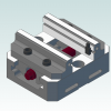
If this requires a sharp point that the bottom of the "V" a chamfer/spot/mill ain't gonna get it. You could lay the part at a 45 deg angle and use a regular endmill. I' done this before by using my machining center as a Shaper, that is as long as you have spindle orientation. I ground a piece of HSS to a sharp point and it worked great in Aluminum (using AL tap magic).2 points
-
The idea is to create the geometry projected to that surface and then drive from that curved geometry that is following the surface. You will want to switch to 3D and do like he said and you should be good to go. You will not normally see 3D as an option when you have 2D geometry, but when you have 3D geometry then 3D shows up as an option in the contour toolpath.2 points
-
Create the center lines for the knurl above the part in 2D mode in the pattern that is required. Then project them to the surface. Then use a contour toolpath with the Compensation type set to "Off" to follow the lines. Set you depth as required.2 points
-
Best thing since sliced bread...period.1 point
-
If it is a simple cone just do the layout with a compass. http://www.pulse-jets.com/phpbb3/viewtopic.php?t=59011 point
-
For a flat pattern? Try Splitting the surface in half and use the chook flattensurf.dll or might have to make wire frame and try the unroll. There are formulas to covert a cone into a flat shape. Been years since I needed to make a sheet metal flat for a cone and would have to dig it our of my old books. If rolling to make the cone take stretch and elongation into account for the material. I worked in a Fan factory when i was in my early 20's and we made all types of exhaust fans.1 point
-
He reached is posting limit for the day and cannot answer us till tomorrow. I agree can be done, but with what I have for the Mastercam file and without knowing a lot more information was just trying to throw something out to get him running like it is setup in Mastercam. Just tying to help him understand why it was not working like he thought it should. We can see if because we have been doing this for a day or two, but for those just getting into this type of work it helps when someone points out things to educate and teach.1 point
-
It's a different way of working Ron...I won't debate the better/worse aspects of it...at times a programmer's hand is limited by other people...that said..his method will work...he just needs to set his 2nd origin to a place that can be successfully picked up and data entered...tooling balls are extremely helpful for just these kinds of pickups... As I use a base pattern for almost all of our tombstones, I have gotten to a point where everyone of them gets a tooling ball location as a base mounting pattern. Any difficult to pick up positions are referenced to the the tooling... We have found that with the post calculating all origins and using hard fixtures as 5th axis, the offsets are generally within a .001"1 point
-
I programmed EZ- Path lathe with MasterCam for years. The best way to approach this issue as Ron mentioned is with Ref point.1 point
-
Cooled table bearings...now we’re talking. Any idea on accuracy specs for the machine, nothing listed on DMG’s site. We have been looking at a Makino DA300, and a Doosan DNM3505ax with glass scales. Makino has there own cell, the Doosan would use a Bot or erowa, I guess the Doosan is pre plumbed for hyd work holding. Is the Siemens or Heid that awesome? I do like our 31i’s, but I’ve always been a fanuc guy, until we made that one Haas purchase . It serves a purpose. Thanks for all the feedback thus far guys, hope you are all doing well.1 point
-
No problem here you go. All I ask is you pass it on to others like i have done for many years on this forum. Pass it on Have a good night.1 point
-
Only thing to add is the -.03 has to be either on the stock to leave on floors or in the depth on the linking page to get the .03 called out on the print since it is projected to the top surface of the part. I also suggest using Model prep to fill the holes before projecting the lines on the top of the solid.1 point
-
Like Ron stated once you select the "projected" line the toolpath will recognize it as a 3D contour. Use Lead In/Out to extend the start and exit of the projected lines. You will notice that the depth options (Absolute/ Incremental) are grayed out as it is a 3D curve.1 point
-
If you do not use a Weldon holder (it has a set screw to hold the cutter into place) the cutter can suck out of the collet as the angular shape is creating downward pressure. Your photo of the cutter has a Weldon Shank for this application. Yes Contour toolpath, multiple passes if you have room and time....it depends on the tolerance and finish etc.1 point
-
Yes better way to handle it.1 point
-
a blast from the past LOL Amazing how much our computers have advanced. 32g is mainstream for a Cad/Cam PC now.. power users run with 128g1 point
-
There is a post switch: linarc$. Set that to '1'.1 point
-
1 point
-
If it's a wireframe 2D contour you can transform your arcs into line segments. If you don't want any arc moves then I guess you can edit your control definition to break arcs.1 point
-
This comes from the Default Settings in the Mastercam Default Operations Files. By "default" this ".Mastercam-defaults" file (there is only 1 default), always "pulls" the coolant settings from "MPFAN.PST". Why? Because that is Machine Definition that is "tied to the Ops file". You have the ability to create a "separate default Operations File", for each machine that you have a MD/CD/PST Combo for. This gives you the ability to have "default settings" which are tweaked for each of your machine preferences. If you want all Operations to default to "Coolant After", then you need to edit each Operation in the "Operations Defaults" file. Pretty simple to have these all set to "After", but it also depends on what coolant options you have on the machine. The default for MPFAN is to use "V9 Style Coolant", not "X-Style Coolant". For that reason, I recommend making an individual copy of the Operations Defaults File, for each machine, and then going through and editing each Operation Type to use the correct default settings. Yeah, it is a lot of work. But it also gives you a ton of control over exactly what your output is. I have been in 100's of shops, and the only thing I can tell you that is common throughout them all is this: there is no "official standard" for how parts or machines are run. Everyone thinks their system is either "perfect" or it is "totally messed up". I happen to think customization is healthy, as it gives you the ability to control exactly what your code output looks like. Like a great majority of users who first start learning Mastercam; you are going to be frustrated that the system doesn't work "like you think it should". I can tell you that the more you embrace how the software is built, and learn how to control it instead of fighting with it, the more efficient you'll be at generating good clean code.1 point
-
Hi Joey, Try looking for pcomment$ or pcomment2 instead. pcomment$ can be called multiple times by a single comment$ call and is used to read in comments, manual entries, machine name, etc. If you write a string variable using scomm$ when gcode$ is 1008 that will save out the operation comment. mpmaster already does this using a variable called scomm_sav to prevent the operation comment from being output in the header of the post, and move it to the first toolchange. You might even be able to get away with calling scomm_sav in pbore2$ where you currently have comment$. Just note that this will only work correctly if your operation comment is a single line. If you want multi-line support you will need use a buffer to store out the comments, in which case I would recommend going through your reseller to get a dedicated post developer like me to take care of it for you Alex1 point
-

Version 1.0.0
304 downloads
The Mastercam 2020 Multiaxis Essentials Training Tutorial is intended for the advanced Mastercam user looking to learn Mastercam Multiaxis programming. A firm grasp on both 2D and 3D machining is required and can be attained by completing the Mill Essentials and Mill Advanced Training Tutorials. The Intro to Multiaxis Training Tutorial covers the different applications that are available by configuring the Rotary Axis Control page including: Rotary axis positioning and Axis substitution. The book also covers the Multiaxis Classic family toolpaths: Rotary, Curve, Swarf, Flow, and Msurf. A special tutorial is dedicated to teaching how to drill and circle mill holes using Multiaxis toolpaths. Specific parameters such as Cut patterns, Tool Axis Control, Limits, Collision Control, Linking and more are described in detail. The contents also describe how to verify the toolpaths using the new Machine Simulation module that combines toolpath backplot mode and material removal mode with collision detections.Free1 point -
Honestly, I cannot do CADCAM without it. I have 4 of the expensive ones with all the LCD features. However, I turn the LCD off because I find it useless. I do program the buttons. I would recommend the one with no LCD and with buttons. They were selling these on EBAY for a huge discount if you qualified as an educator. I made up a phony check stub in MS Excel saying I worked at a college and got the discount. Normally $400. Discount $279.0 points
-
As rigid as a "Wet Cardboard Box"......!!!!0 points
-
Haas UMC 750 and FTW.....0 points
-
If you shout just a little louder JP will be able to hear you...0 points
-
Well, you can't have everything....0 points
-
All good John just being the crazy person in the room is all.0 points
-
:cough: :cough:0 points