Leaderboard


Popular Content
Showing content with the highest reputation on 06/17/2020 in all areas
-
Also, having #6001.6 = 1 helps the cause so it doesn;t disappear right after the cycle is complete.2 points
-
#4 - There's a conflict between MCforSW's Backplot and SolidWorks' Enhanced Performace graphics setting. (It's at the bottom of the System Options / Performance page). Uncheck that (I'm not sure what you're losing by doing that) and Backplot should co-operate.2 points
-
We have always had to set this on our MXs to keep the data in the 100 plus macro variables after m301 point
-
Ive milled pure tungsten. It wasn't bad customer requirement had millet dry and actually ran quite well I used CID tools I guess I would say 80 to 150 surface feet. Copper will probably make it a lot more abrasive1 point
-
Run a few different cycles that also write data to #139 and see if any of them will still write. That will help you narrow your search down to a problem local to your program, or more global ie parameters. That's a good point, we have a 31i that way. I usually put a M1 in between my cycles and turn the block skip when trying this stuff out.1 point
-
You might not necessarily be able to see it. The PMC can process data way faster than it can update the HMI display.1 point
-
It worked and now it doesn't... ??? I'm left with what did someone change1 point
-
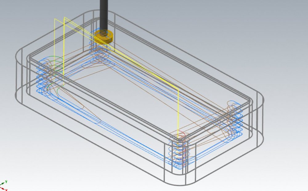
Optirough does not allow undercutting, no. BUT- on a shape like this, where we just have to avoid the lip around the boundary, we could just neglect to tell Optirough the lip is there, set our Minimum depth to be the underside of the lip with a stepdown of the thickness of the slotting tool, and add in large entry and exit values in the Linking page, and voila- dynamic rest roughing with a slotting tool that also properly clears the lip on entry and exit. Now, this is just using a Roughing Tool setting in Stock rest material. If we have a complex stock model, with maybe some variable stock in floor areas, we'd need to somehow remove the 'lip' of stock to allow this method to work correctly and ensure Optirough continues to ignore geometry and stock higher up than the lip. In a case like that, we could use a ghosted facing operation to 'clean' the stock down to the underside of the lip, and then generate a stock model for our Optirough based on this ghosted facing op.
 1 point
 -
I've not see one anywhere, let alone the wild. Chinese machine is gonna be a tough sell these days in the US at least.1 point
-
Force your arcs into quadrants and use G60.1 point
-
I've only seen the VMCs but everyone I know of intends to only buy more.1 point
-
Point toolpath to rapid to deepest Z 1 dynamic path at deepest Z Use Transform for required depth cuts Point toolpath at final Z for safe retract motion1 point
-
If the arc isn't long enough the cmm may not have enough data to calculate it1 point
-
Planes is your answer. Just need to establish a good Pick up point to control your Zero from. I suggest using a Tooling ball. A custom post would be the easiest solution, but it can be done with a standard Fanuc post, just have to map your pick up for the work offsets out. Once you do then you should be good to go.1 point
-
Use dynamic contour like your thinking, but make the ref points at in and outs at the depth your cutting. Make the clearance moves, restract and everythign in the window you're cutting in. Then make points tool paths to get into the cuts and out of the cuts. I have done this for used using under cut tools. I did a manifold with some 10" Gauge length Sandvik tools for a customer that has HSK-100 on their Mill/Turn. They were impressed how smooth and nice the cuts were in the 17-4 PH SS we were cutting. Here is a screen shot of the tool: This was round undercut, but the shape doesn't matter.1 point
-
My employer bought small 5X gantry mill from them in 2007. It did not go well and we gave it back to them after a year of struggle. There are a few shops around here that run their 3 axis gantries and like them. They are still in business http://www.mightyviper.com/1 point
-
I don't know anyone who's ran one or even seen one. Are they now a defunct company? I think they used to have an HQ in SoCal.1 point
-
Amazing people cheap on the important stuff then wonder why your fighting to make good parts. I understand the user name now. Best of luck getting it sorted out.1 point
-
FWIW, the last MX-520 I did a ballbar test on I ran it at 5000mm/min and it was round within 5-6µ.1 point
-
Yes I agree if you leaving .05 stock for a .031 endmill and trying to cut 2" deep no settings in the world will overcome that as bad machining process. Don't laugh I have seen it tried.1 point
-
Did you give them the same amount of info that you've given us?0 points
-
sorry, version 20190 points
-
Version?0 points