Leaderboard


Popular Content
Showing content with the highest reputation on 07/14/2020 in all areas
-
On Sinumerik the machine kinematic is irrelevant. Just register correctly the tool so the controller can compensate it have your succession of codes correctly and with same code will work on all of them regardless of kinematic...u can even do 5x On a fanuc u can do it but not as easy and elegantly.. N1701 (RAD 1 WIN 1-COMPUTER COMP/DIA.5) #601=10. #602=#600*COS[#601](X SHIFT) #603=#600*SIN[#601](Z SHIFT) G65P9999C180.X-#602Z#603U54.D55.(G55) G55G90G00A0B0C0 G43.4H144D144Z8. X-38.5526Y12. A0B#601 G43.1 G68X0.Y0.Z0.I0.J0.K1.R270. G68X0Y0Z0I1.J0.K0.R80. M7 M198P6531 M9 M3012 points
-
See attached..

 2 points
 -
1 point
-
ive got a square pocket to put in a part im making. it is .438 square and about 4 inches down right against a vertical wall in 316 stainless. It has a .4 hole through the center so theres not much coming out but the corner rad is .125 so I can only use a .25 endmill that is 6 in long. the pocket is actually only cutting about .7 deep and needs a square corner so I cant broach it. im cutting it now by spiraling down about .01 per pass and its working but tapering about .01. ive made the corners about 135 in mc so it can contour even though its very little. any ideas?1 point
-
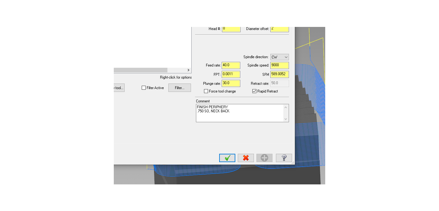
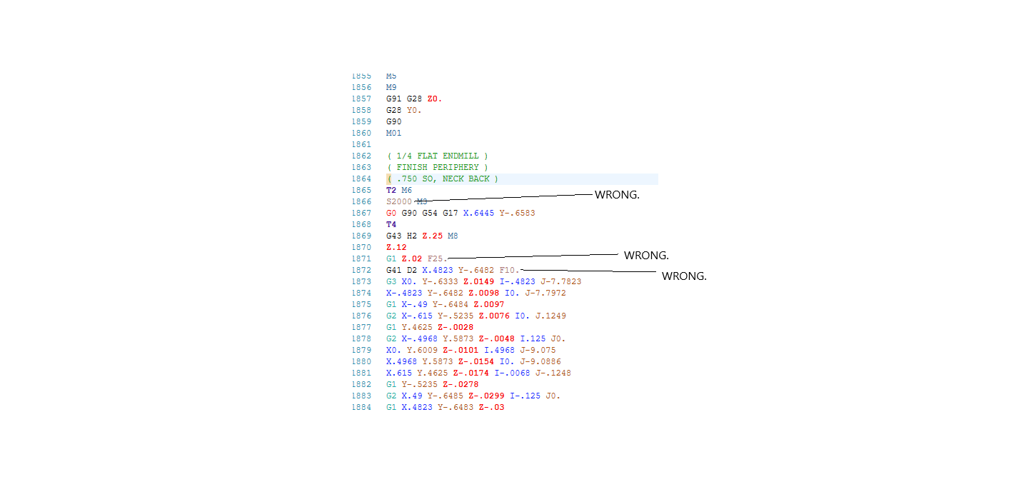
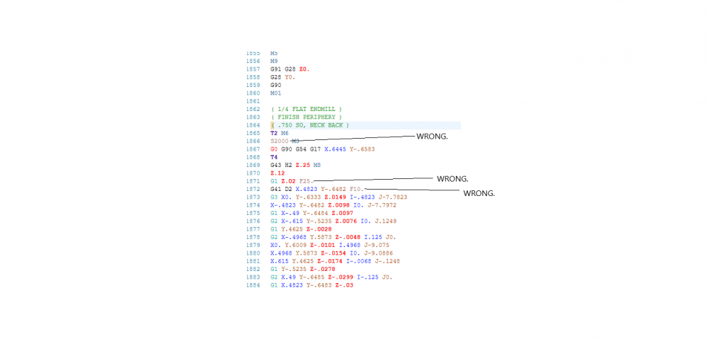
I've got a file with 15 ops, and at one point it posted every single op to "default" RPM and feed values instead of what was programmed.

 1 point
 -
The easiest way to find center of rotation, is to indicate the table flat at the top and zero your x-axis and z-axis at the center of the table and face of the table respectively. Then rotate your table 90 degrees, and find the x-axis location of your table face, and then the center of the table in z. Between those two measurements, you should be able to figure out your center of rotation. Then just figure out what those distances are from machine home, if necessary. Hope this helps. Brent1 point
-
Thanks again for the tips. I will let you know what happens when I get to it. I've been moved to another hot job for now.1 point
-
1 point
-
Depending on the version of Mastercam you are using I'm pretty sure there are issues with this chook. Its been a while since I've used it as well but I don't think it worked in Mastercam2020. I remember the training/book department said there were issues with it. I have not tried it in Mastercam2021 yet so I cant say if it works in that version.1 point
-
I had that as a problem before with a 5 axis post and using axis sub toolpaths. Never found out what the solution was as I didn't own the post and was locked out of most of it. I will dig into it when I get a chance.1 point
-
I see this with Catia models all the time. I've grown to hate Catia and I don't even use it.1 point
-
I would try changing the direction of the rotary from CCW to CW or vice versa, my guess is your rotary direction for Clockwise/Counter clockwise is Bass Ackwards1 point
-
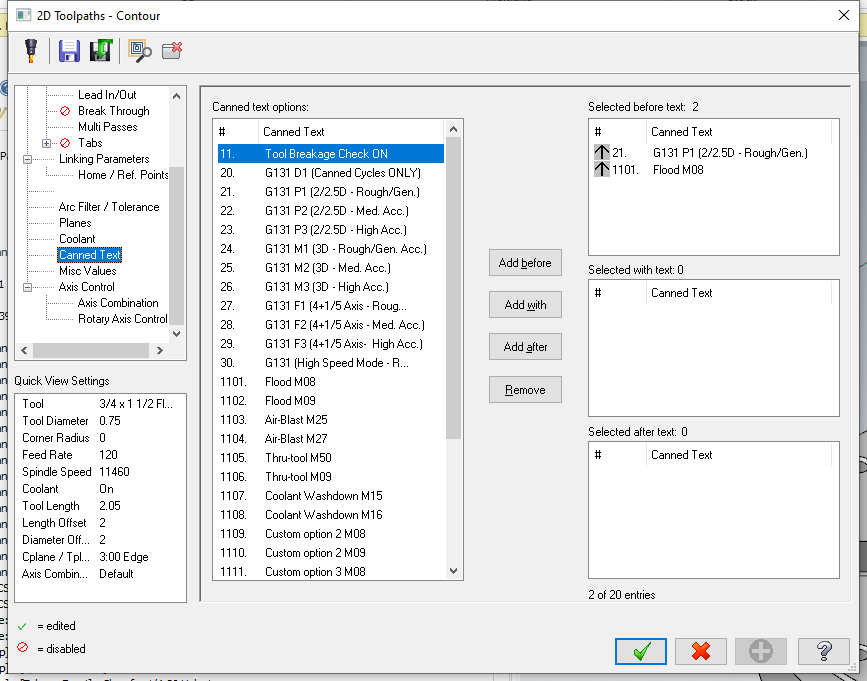
You could use Canned Text instead of Misc. Int./Misc. Reals as well. I think it's a cleaner method.
 1 point
 -
I ran out of space here so I uploaded them to an image hosting place https://postimg.cc/gallery/9M2MTn4 So you basically have to make a macro called MANUAL_ENTRY with the custom gcode dialog. There is one box to add a new line up at the top and at the bottom there's a box that says add codes. So insert like 10 lines and copy the example1 point
-
Funny I programmed that DMU 80 in a 3+2 process and just shifted the T-C planes the difference of the gauge length. NX guys were tripping out wondering how i was able to get that done in Mastercam.1 point
-
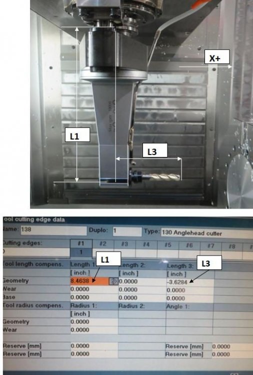
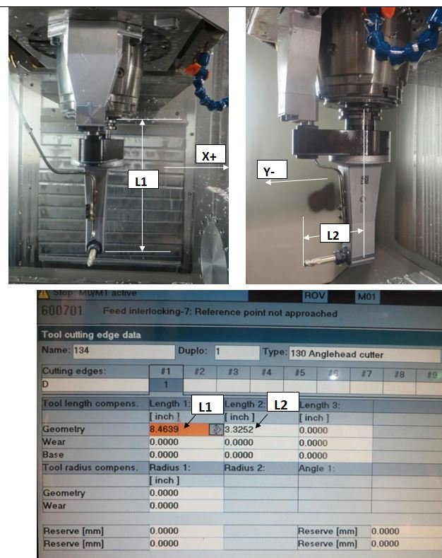
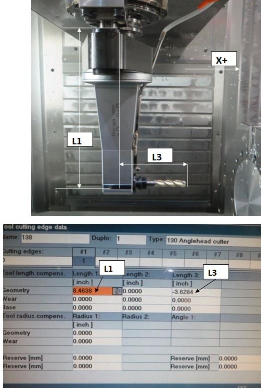
Get a good post and call it a day. Did a DUM80 FD machine RAH job and got to the point I needed to spin the RAH 116.486 degrees along the Spindle Axis. None one could handle it. I tricked it in and still got good code because the post was done correctly. I am about to put a RAH on a 90 degree head facing upside down for a customer. Here is a screen shot of what I going to be attempting to give you an idea. The main spindle is HSK-100A. Here was the DMU80 RAH Setup to give you an idea what is possible with the right post.1 point
-
You need to decrease the tolerance to get more output when doing C axis work if not using the G12.1 or G112 process. Look for a Switch in the misc integers settings to change the output to get Polar Interpolation and see if you get better results.1 point
-
I usually extend the surface. If it's against a wall you can do pencil or project with a few multipasses1 point
-
Josh not exactly what he was looking for. You doing it to a radial surface and he needs it to a conic surface. Need to draw the solid and then work from the conical surface. The trick is getting the start and end points, but not really all that hard once we do some basic CAD work. Heavy Metal I have made the solid without the simple stuff and detailed the levels and the solids manager to hopefully help you on your path to make your own solid. I went ahead and put a toolpath it to give you an idea how you could go about it. Not that is all that good just a way I would try to approach it. Mastercam file Here is a video of that part being cut in Machine sim. I also made a video showing how i moved the arcs to the start and end of the slots to help with model creation. Maching Slot in Machinesim Slot Creation start using Dynamic Transform1 point
-
since we cant extrude cut normal to a surface we can use fence surface to accomplish this task, and from there the surface can be used to cut the solid. First project the shape onto the surface (Transform Project) then convert the multiple entities to 1 spline (on the wireframe tab, click the drop down for Spline Manual and choose Spline from curves, choose the projected geometry and make sure to choose delete original curves so you are left with 1 single spline) Then create a surface from the face of the part, and use a Fence surface to build the slot. (found on surface tab, called Fence) which will get you to the point i am at in the image below.. Then the last step is if you want the slot cut through the solid to go to your solids tab and choose Trim to surface (found under the trim to plane dropdown) if the above doesn't make sense then if you can send your file i can put together an example.1 point
-
Open Verify, File>Options>Graphics1 point
-
Wear comp and computer comp are identical toolpaths ... the only difference is you get a G41 /G42 and a diameter offset posted when you select Wear Comp1 point
-
No need to pay someone for a RAH post... IF... You are using a 3X machine, with a Fixed Position, RAH attachment. (Either Bolt-on, or Tool-Changed, as a tool in the magazine.) The only case where you would need to have a post "build" is in the case of a "programmable" RAH. This is where you want to have "C-Axis" output, and have the program change the rotation of the head inside the NC code. (And really, the post builder just takes the 4X Router post, and converts it to a Mill Post. This is 10 minutes work tops for a decent post writer.) If all you are doing is mounting a RAH, then the Machine Definition, in combination with the Generic Fanuc 3X (or 4X) Mill Post is all you need. You build a 3X RAH, by going into your Machine Definition, Right-Clicking on the "Spindle" component, and "appending" an "Aggregate" component. Once you've added the Aggregate Head, you need to Right-Click, and add a "station". Think of a "Station" as a specific "orientation" of the RAH. (Where does the Tool point when the RAH is mounted?) With a 3X Machine Definition, with the proper Aggregate/Station/Tool defined, the only other thing you have to enable is "Translate NCI with machine aggregate" check box (inside the Control Definition). That's it. No special Post required. Just start a new tool path (make sure the WCS is set to the "machine view" (or Top in a "standard" VMC configuration), and the Tool Plane is oriented to "face" the feature on your part. After starting the path (Contour for example), Right-Click in the "Tool selection" area (white space) and choose "Get angled head". As long as you've got it configured correctly inside the Machine Definition, it just "works", out-of-the-box. This is one of the few "features" in the Machine Definition that does work correctly, out-of-the-box.1 point
-
I've looked into it quite a bit, but no, not really... The general rule of thumb is to use blend when it is a problem that flowline can't handle. There is a button on the flowline interface called "single row only" that trys to force Mastercam to evaluate all your surfaces as a "single row" and eliminate the gap retract moves at the surface edges, but it is hit and miss... Your choices are to build wireframe and use blend, or to attempt to rebuild the surfaces and try to get flowline to work... Most of the time I just use Blend, or sometimes Surface Finish Contour, depending on the shape I need to machine. HTH,1 point
-
Yes, it can machine a single surface without having to create any wireframe geometry. It will also do a good job on a set of surfaces, if all the surface U,V curves flow in the same direction... Blend is much better for sets of surfaces, but it does require you to generate two chains (can be as simple as two lines, or even a rectangle and a point...). There is also no "roughing" option in Blend...1 point
-
If you have very deep pockets, buy a few Yasda's. Then they won't be deep anymore....0 points
-
I tried that ….it walked all over the place.the square hole looked like gumbys head! we had great success on the setup pc which was aluminum.0 points


.thumb.jpg.e1ed32e8dc33a68b1f20806bb5d55e08.jpg)