Leaderboard


Popular Content
Showing content with the highest reputation on 12/16/2020 in all areas
-
I'm looking at RStewart's file to try and get some clarity on what's going on, but just an extended note on these system Configuration switches, which are "Tool starts from home position after tool change" and "Go to home position on tool plane change", located under the Simulation tab: These switches initially sound like a magic fix for issues with simulating the transition of tool positions between 3+2 operations without going through the step of making a big multiaxis link operation that consumes them all. What they do is look at the positioning set in the Home/Ref points subtab of Linking Parameters, which I believe ends up in World coordinates. For something like a head-head machine, you could eventually get to a decent replication of motion if you spent enough time matching up these position settings between each operation, but quite honestly it's time-consuming and in the end it still doesn't represent what the post will actually do for your machine's transition motion. My recommendation would be to leave them off or make sure they're off unless you have a very deep understanding of what they'll do. The better choice to control this behavior for 2020 and earlier is the Control Def edit which JParis alluded to, which is to go into the machine control definition, Linear section, and set Rapid Motion to Linear Interpolate at Maximum Feedrate. What this does is simply give a 'free move' upon transition between toolplanes rather than trying to physically drive the tool between the end of one op and the start of another in some manner. Because we have no knowledge of how each post might handle the transition code at this stage, (and each post WILL handle it differently), not trying to approximate this transition isn't really a big deal. And if we needed to explicitly control it, we could still build a multiaxis link operation to ensure we get 100% apples to apples. From 2021 onward, we no longer require that the user change this Linear setting in the Control Def to get the behavioral change- we simply give this 'free transition move' between all 3+2 operations as default. Note that none of this is the source of RStewart's particular issue here, but is just general information on some solutions for tool gouges when simulating between toolplanes!3 points
-
I find at times I have to use large retract numbers(25") to stop those collisions...then set back to my standard 1" prior to posting The suggested settings for a control def don't always work2 points
-
Your O9833 looks similar to ours. O9833(REN SPIN OFF) G65P9724 #148=0 #149=0 #2=#5043-#116 #4=0 #3=#2-[.10*#129] N2 G04X.1 G31Z#3F[100*#129] IF[ABS[#5043-#116-#3]GT#123]GOTO5 G0Z#2 IF[#4EQ4]GOTO4 IF[#4EQ0]GOTO3 #3001=0 WHILE[#3001LT9000]DO1 END1 N3 S500M3 #3001=0 WHILE[#3001LT1000]DO1 END1 M05 #4=#4+1 GOTO2 N4 #[3006-[[#120AND8]/8*6]]=1(PROBE SWITCH OFF FAILURE) N5 G0Z#2 M99 Our probes activate once they enter the work area and turn off a certain amount of time (30 seconds?) after they leave the work area. You may need to set/reset the probe parameters on the probe itself to get it to work.2 points
-
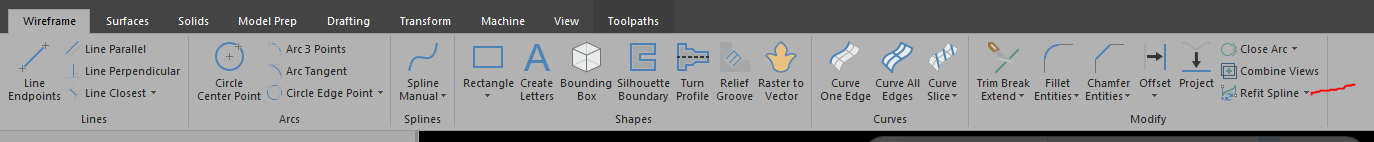
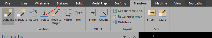
1st I simplify splines (wireframe-drop-down at refit spline-select simplify-select all geometry-delete original) This might take some time. 2nd transform-project to z 0 3rd shift plus left click on entity to see if chains are closed, find breaks in chain and trim entities or draw lines or arcs to close chains. I hope this gets you going in the right direction

 1 point
 -
Try dumbing down the file size by leaving your chain geometry and toolpath and getting rid of everything else like the. Jpg. This should make the file size small enough to attach here.1 point
-
Would something like this help? I searched for 'D-Sub 90 Degree Adapter'.
 1 point
 -
Here is a typical O9832 I see. I don't see anything in there that isn't necessary besides the comments. When starting a probe, It's best to enable ALL the things it may need to ensure proper use so the resulting data is not corrupt. Renishaw has been doing this for a long time. There is reasoning behind what they do and why they do it. That doesn't mean their stuff can't be improved upon though. Be cautious when making large scale changes. O9832(REN*PROBE*START) (F-4012-0519-AA) (COPYRIGHT*1990-2017*RENISHAW*PLC.*ALL*RIGHTS*RESERVED) (-->USER*M/C*START*CODE) M19 (<--USER*M/C*START*CODE) () #3=1 #6=2 #8=1 M98P9724 N1 #2=#5043-#116 #4=0 #32=#2-[0.10*#129] () GOTO4(DELETE*TO*ENABLE*MULTI*PROBES) () #147=#147+9832 IF[#147NE[9832+2]]GOTO2 M98P9712 GOTO9 N2 IF[#147NE[9832+3]]GOTO3 M98P9713 GOTO9 N3 IF[#147NE[9832+4]]GOTO4 M98P9714 GOTO9 N4 #31=0(PROBE*STATUS*ON*CHECKING*1=ON/0=OFF) M5 N5 () (-->*PROBE*ON) IF[#5NE#0]GOTO55 M19 N55 M108(PROBE*ON) G04X1.(PROBE*DWELL) (<--*PROBE*ON) () IF[#5NE#0]GOTO9 IF[#31EQ0]GOTO9 G65P9725Z#32F[100*#129] IF[ABS[#5043-#116-#32]LT#123]GOTO8 G0Z#2 IF[#4EQ8]GOTO7 #4=#4+1 GOTO5 N7 G65P9700E380. N8 G0Z#2 N9 #147=#0 #149=0 IF[#23EQ#0]GOTO10 POPEN N10 M991 point
-
Would normally go straight to HSS, but not if this material is abrasive... Dead sharp inserts specifically designed for aluminum is probably your best bet1 point
-
I agree with everything said above. I don't post a lot on here, but have learned a lot from Ron just from reading his posts. You have given me some Ah Ha! moments and helped me more than you can know. I have been watching the cam instructor series and look forward to learning from you for years to come!1 point