Leaderboard


Popular Content
Showing content with the highest reputation on 01/10/2021 in all areas
-
Thanks a lot for all the information. This put me in to the right course. I think we are getting closer to fix our problem.2 points
-
The #19703-#19705 parameters are for when the top center of the pallet are not perfectly mechanically aligned with the intersections of X, Y, and Z centers of rotation respectively. So for example on a Matsuura MAM72-100H which is a horizontal 5-Axis we have an X, Y, Z, and an A, and B rotary configuration. A rotates around X, and B rotates around Y. A is the primary tilt axis and B is the secondary rotary axis. #19700 = COR X #19701 = COR Y #19702 = COR Z #19703 = NOT APPLICABLE to machines with A Axis #19704 = Distance from COR Y to the top of the pallet. #19705 = Distance from COR Z to the intersection of the imaginary centerline of the rotating pallet. These parameters HAVE to be correct. If they are wrong, you will chase part deviation until the cows come home and you may never get it. When I'm troubleshooting these issues I get a Master tool... a REAL one not some end mill stuck in a sidelock endmill adapter. The one I use is a BigKaiser BigPlus Master Tool traceable back to NIST. I use ONLY a BigPlus because I want to eliminate variables. A non dual contact tool is a variable. I don;t like variables. They add to the confusion of solving problems... but I digress. Next I measure the Master tool in the machine's tool measurement system. If it is less than 4µm, then I call it good. If it's more than that I recalibrate until it's between 0 and 4µm. I say 4µm because that's the standard accuracy of most tool measurement systems. Once that's judged to be good then I look at the flatness of the table at home. If it's off at all in the tilt or rotary axis I'll reset the 0 on those axes. If it's off more than spec in the theoretical axis I call service. If things are good so far, then I get out the granite square and test bar and check squareness, perpendicularity, etc... if after all that, things are judged to be within spec, then I start figuring out which axes are off. Like I said previously, Z is the usual culprit... at least for the majority of the error. 187.9µm sure seems like an awful lot of deviation. When the machine was new were the head and the saddle in two separate pieces then assembled onsite? Anything over 100µm throws up a red flag for me and I start checking machine geometry at that point to make sure somebody didn't miss something somewhere. The values that go into the WSEC Table will be the amount of error that is present between the perfect location, tilt, rotation, and orientation of the part/origin and the actual location(x, y, z), tilt(a), rotation(b), and orientation(c) of the part/origin in addition to the tilt (A) and rotary (B) angles at which the error(s) were measured. Using the WSEC table or not will depend entirely on the situation and type of error present. If I only have X, Y, Z, and secondary rotary error, I'll typically just use my G54/Work Offset. If I've got primary tilt axis error or theoretical rotary axis error then I will use my WSEC table. The values going into #19703-#19705 will depend on the kinematics of the machine. I'll speak only to table/table configuration machines here; A/B kinematic machines will have values in #19704 and #19705 A/C kinematic machines will have values in #19704 and #19705 B/C kinematic machines will have values in #19703 and #19705 The codes you're asking about are NOT Nigata specific functions/codes. They are FANUC functions/codes. They should be present it your yellow FANUC Manuals. #19700-#19705 information is in the Parameter Manual (30i/31i-B Series - B-64490EN_03) G43.4, G54.4, and G68.2 are in the FANUC Common to Machining Center/Lathe Operator Manual(s) (30i/31i-B Series - B-64484EN_03) HTH2 points
-
G54.4 WSEC is what it's name implies Work Setting Error Correction. Ti calculates it's positions from the #19700-#19705 parameters (kinematic center of rotation plus table offsets)Standard offsets handle things in a generally linear fashioned. G54.4 can compensate not only linearly but spatially as well. It's not "like" any other function. 68.2 TWP It calculates it's positions from the #19700-#19705 parameters as well. It calculates it's angles based on type. Euler type angles are best. Rotation around primary Z(I), rotation around primary X(J), then rotation around new Z(K). G54.2 RTDFO calculates it's positions from either the common offset or the workoffset PLUS the data in the RTDFO table (distance from COR to part origin). G68.2 is more powerful than G54.2 G43.4 is TCP. It calculates it's positions from the #19700-#19705 parameters also. It is "usually" reserved for rotary type toolpaths, but it's not limited to them. You may not use G54.2 in conjunction with G43.4. They would conflict. You may use G54.4 and G68.2 in conjunction with G43.4 The error you speak of is that mm or inch? Your kinematic positions MUST be correct of you WILL have size and or location error on parts. You MUST turn things ON/OFF in specific order or else things will not function correctly.2 points
-
Was doing some documentation and parameter stuff today and figured I'd share. FANUC gets a bad rap for a number of reasons, many reasons are self inflicted, however that doesn't take away from the power that is available on machines with Custom MACRO B. Nearly everyone knows G10 (FANUC's key to write to tool offsets, work offsets, parameters, etc...). It's not the only way though; Another way to write/access work offsets; Common(EXT) [#_WZCMN[1]]=-10.1234 (WRITES -10.1234 TO THE COMMON WORK OFFSET FOR X) [#_WZCMN[2]]=-8.7654 (WRITES -8.7654 TO THE COMMON WORK OFFSET FOR Y) [#_WZCMN[3]]=-16.5432 (WRITES -16.5432 TO THE COMMON WORK OFFSET FOR Z) [#_WZCMN[4]]=-1.234 (WRITES -1.234 TO THE COMMON WORK OFFSET FOR THE 4TH AXIS) [#_WZCMN[5]]=54.321 (WRITES 54.321 TO THE COMMON WORK OFFSET FOR THE 5TH AXIS) G54 [#_WZG54[1]]=-10.1234 (WRITES -10.1234 TO G54 FOR X) [#_WZG54[2]]=-8.7654 (WRITES -8.7654 TO G54 FOR Y) [#_WZG54[3]]=-16.5432 (WRITES -16.5432 TO G54 FOR Z) [#_WZG54[4]]=-1.234 (WRITES -1.234 TO G54 FOR THE 4TH AXIS) [#_WZG54[5]]=54.321 (WRITES 54.321 TO G54 FOR THE 5TH AXIS) G55 [#_WZG55[1]]=-10.1234 (WRITES -10.1234 TO G55 FOR X) [#_WZG55[2]]=-8.7654 (WRITES -8.7654 TO G55 FOR Y) [#_WZG55[3]]=-16.5432 (WRITES -16.5432 TO G55 FOR Z) [#_WZG55[4]]=-1.234 (WRITES -1.234 TO G55 FOR THE 4TH AXIS) [#_WZG55[5]]=54.321 (WRITES 54.321 TO G55 FOR THE 5TH AXIS) G54.1P1 [#_WZP1[1]]=-10.1234 (WRITES -10.1234 TO G54.1 P1 FOR X) [#_WZP1[2]]=-8.7654 (WRITES -8.7654 TO G54.1 P1 FOR Y) [#_WZP1[3]]=-16.5432 (WRITES -16.5432 TO G54.1 P1 FOR Z) [#_WZP1[4]]=-1.234 (WRITES -1.234 TO G54.1 P1 FOR THE 4TH AXIS) [#_WZP1[5]]=54.321 (WRITES 54.321 TO G54.1 P1 FOR THE 5TH AXIS) Tool offset registers (Memory C by var. name – D-Comp – Param. #5004.2=1): These registers may be read from and or written to. H-GEO H-WEAR D-GEO D-WEAR T1 [#_OFSHG[1]] [#_OFSHW[1]] [#_OFSDG[1]] [#_OFSDW[1]] T2 [#_OFSHG[2]] [#_OFSHW[2]] [#_OFSDG[2]] [#_OFSDW[2]] T998 [#_OFSHG[998]] [#_OFSHW[998]] [#_OFSDG[998]] [#_OFSDW[998]] Tool offset registers (Memory C by var. name – R-Comp – Param. #5004.2=0): These registers may be read from and or written to. H-GEO H-WEAR R-GEO R-WEAR T1 [#_OFSHG[1]] [#_OFSHW[1]] [#_OFSRG[1]] [#_OFSRW[1]] T2 [#_OFSHG[2]] [#_OFSHW[2]] [#_OFSRG[2]] [#_OFSRW[2]] T998 [#_OFSHG[998]] [#_OFSHW[998]] [#_OFSRG[998]] [#_OFSRW[998]] Pretty much everything has a name. In the FANUC Series 30i-MODEL B Common to Lathe System/Machining Center System OPERATOR'S MANUAL B-64484EN_03 they can be found in the Custom Macro section. HTH1 point
-
I wish I had seen this sooner I did a job several months ago where this technic would have saved me a bunch of programming time and produced much cleaner code1 point
-
Send me a file you struggled with and let me see if I can give you a different way to look at it. Not making any promises, but you seem like a hard working intelligent person who wants to be better. I want that for you like I do any person doing Manufacturing. We are running out of people engaged in this profession so I am always looking to engage more and if I can help you then you help others then we grow those engaged. [email protected]1 point
-
1 point
-
Look to online training with one on one aspects or hire a contractor to come in and give them some of your hardest part and make them teach you as part of it.1 point
-
This worked better than I had hoped. But next time I will put more of the finishing on the fixture as when it got thin it rattled a little.1 point
-
Powerful stuff here1 point
-
I'm nobody special and I know how to do those things so... @byte me, Mastercam has no kinematic awareness. If it did, we would not need Misc. Int./Misc. Reals to dictate tilt/rotary preferences/behavior.1 point
-
Here ya go Colin. Yes,, you can query individual bits.. To change them, you still need to go the G10 route. Parameter Reading (Sys commmon, path or machine group) #i = PRM [#j] Parameter Reading (Sys commmon, path or machine group parameter bit number spec.) #i = PRM [#j,#k] Parameter Reading (Axis or spindle parameter) #i = PRM [#j]/[#l] Parameter Reading (Axis or spindle bit parameter) #i = PRM [#j,#k]/[#l]1 point
-
IIRC, you can.... PRM [1,2] where the number after the comma is the bit number you want to query. Read Mike Lynch's article on it. It gives a good basic overview. https://www.mmsonline.com/columns/accessing-parameter-values-from-within-programs I have seen the Fanuc documentation for this function somewhere at some point in my life, possibly in one of the robodrill books. I can picture it, just can't place where I had access to it at one point in time. It's not in the standard 31i pdf manuals that I have on my computer at the moment... Just a note for everyone who isn't fully up on this subject but are curious, and will start poking around. Not every parameter has a numeric variable associated with it. Notably, I don't think the kinematic offset parameters above that Colin as referring do. Maybe the do and I just haven't ran across them. But using the PRM[] function to query them is a much less confusing method as you are querying the parameter itself and not a # numerical variable with a different number that references the parameter you want to adjust.....1 point
-
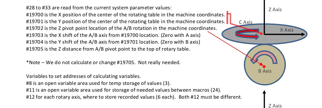
Thanks for this James. I recently found another eastear egg in a Blum Probing Routine. Looks like with the Fanuc 31i, you can read parameter values without using the "numeric variable" that is associated with that value. ( AKTUELLE KINEMATIK WERTE ) #31=[PRM[19700]]/#20(=#19700) #32=[PRM[19701]]/#20(=#19701) #33=[PRM[19702]]/#20(=#19702) #28=[PRM[19703]]/#20(=#19703) #29=[PRM[19704]]/#20(=#19704) #30=[PRM[19705]]/#20(=#19705) I have not seen any documentation yet explaining what the limits of this [PRM[ ]] syntax are. It would be awesome if we could read individual "bit" settings, but I've only ever seen it applied to these specific #19700 series parameters.
 1 point
 -
Like this size???0 points
-
Oh man. I love AE chest offs0 points