


Leaderboard


Popular Content
Showing content with the highest reputation on 02/12/2021 in all areas
-
Hope you like it I'm hooked, and I have trouble going back... But I'm biased! You're correct, this is all MW tech running this, but it is a Mastercam-only creation. I designed it and we created it just for our use. It's really a big decision tree in the background that chooses the engine based on your input choices. You're not only getting access to not only the surface-based technology you're used to (Morph, Parallel, Along Curve, Project Curve, and now Flow), but also a Geodesic-based algorithm, which is what gives us automatic boundary-based patterns, N guide curve input, etc. There's a bit more magic happening of course, like if you have two curves selected and have it set to Guide, you'll get a Morph-style geodesic calculation and such. The real goal was that you feel free to just toss input in and you'll get a good toolpath out. We have a few more tricks up our sleeve for the future, but I'm really, really happy with how it came out.5 points
-
I agree, I like to quote 8 to 9 times the cost of the part in 4140. If parts made in 4140 run at 600 sfpm and Incoloy 100 sfpm so that's 6 times slower and then indexing time, operators are constantly changing inserts then there is "pucker factor". The cost of the part operators are measuring and remeasuring the part to make sure its right, it all adds up.3 points
-
My experience is with Incoloy 925 but I'm sure it similar enough. I would use solid carbide endmills Incoloy likes sharp tools so if you have to use inserts get ones with positive geometry. I've switched from indexable cutters to endmills and shaved hours and hours off of the parts we make. When using indexable because your cutting so slow if your machine can handle it increase the depth of cut if possible. Be prepared to use a lot of inserts. For example: Standard Z level roughing took 30 hours, same feature using Dynamic OptiRest took 7.5 hours. Huge difference. The endmill lasted the entire time never had to change it, in fact it's still in the machine. It was Kennametal Harvi 1 HPHV1000S4400 KCPM15. I didn't even have the best coating for Incoloy on that endmill. 110SFPM at .005 fpt3 points
-
If you've never cut it be careful with your quote, don't get caught with you pants down. Its not difficult to cut once you learn what it likes, but tooling cost will be high and you're not gonna go super high feed. I never cut it with anything more than 5 flutes, but I can see where more flutes would be very helpful, like Ron said. This was about 6 years ago for me, but IIRC, we had great success with Kennametal Harvi tools on the mill, and for the roughing on the lathe we were using Walter inserts. Things may have changed since then, but the ticket was low and slow. I think we were running about 1800rpms on the mill. First day on a new job boss calls a meeting and he says "we just got a large order for all inconnel… I had never heard of the material...ooff!2 points
-
High Feed or 7 to 9 Solid Carbide cutters. I have seen some able to get up to 220 sfm and handle it for about 1 hour cut time.2 points
-
Hey Colin, I didn't take it that way...all good. Thought I should supply some info on me. I will do my best to go thru the inspection plus book. The Haas youtube channel is such a great service to us looking for answers via video. Always checking that page out.2 points
-
Version 1.0.0
11,438 downloads
These are the files used in Mastercam 2021 Training Books and eBooks. Click the "Download this file" button to the right to download a .ZIP file containing all files used in all In-House Solutions books for Mastercam 2021. Note: A server issue is preventing the full collection from downloading at the same time. Select the download for the individual books you need after clicking the download button. These files are referenced in the following titles: Mastercam 2021 Mill Essentials Training Tutorial Mastercam 2021 Mill Advanced Training Tutorial Mastercam 2021 Lathe Training Tutorial Mastercam 2021 Multiaxis Essentials Training Tutorial Mastercam 2021 Multiaxis Advanced Training Tutorial Mastercam 2021 Solids Training Tutorial Mastercam 2021 Mill 2D Professional Courseware Mastercam 2021 Mill 2D Advanced Professional Courseware Mastercam 2021 Mill 3D Professional Courseware Mastercam 2021 Lathe Professional Courseware Mastercam 2021 Multiaxis Professional CoursewareFree1 point -
Good luck like I said on the official forum need to reach out to your dealer. Asking for a post here is not allowed.1 point
-
Asking for a Post is not allowed on this forum. Contact your reseller.1 point
-
Yon need a machine with the rpm, many of our mills only have 4k spindles but we have two new Mazak J400 that have 12k spindles so I would like to give it a try. When it comes to turning it spins too fast to not use a tailstock, it would have to be application specific. GreenLeaf seems to have impressive speeds and feeds in Incoloy. Turning 600-700SFM / .008”-.010” IPR / .050” - .080” DOC - 7-8mins of tool life Milling 2000SFM / .004” - .005” IPT / .050” - .080” IPT.1 point
-
Believe it or not, I see that on occasion going into a Matsuura as well. In my 5-Axis training kit; JM Performance high strength pull studs, BigKaiser Hydraulic and ER Collet adapters, Rego-Fix precision collets, Frasia, Kennametal, and Harvey cutting tools, Raptor Adapter plates and risers, and Schunk KSC vices in a rolling Pelican Case. I can't very well recommend customers buy quality stuff if I roll up with run of the mill garbage now can I?1 point
-
Ceramic endmills?1 point
-
I'm of the opinion that if you buy that kind of machine but can't afford to make it do what it was designed to do, you shouldn't even be getting in the game in the first place. May as well put radials on an F1. Seriously.1 point
-
The costs on the backside will be ten times that at least per year.1 point
-
Buying a 5-Axis machine without TWP, TCP, WSEC... all in an effort to save a few grand... I just don't get it.1 point
-
Nice work and was alogn the lines I was thinking it would need to be done. Thank you for sharing, but like you said anyone should test and use at their own risk. I added two finish operations to the sample file with the same tool and different tool to allow me to check null tool changes and tool changes.1 point
-
Yes used that brand before and seems slow for their cutter. Might try 110 to 130 sfm and see what kind of tool life you get. Watch the ROC with a 7 flute more than 5% and you might have issues with building up the chips on the tools. 1000 psi with TSP is a night and day difference that just regular flood.1 point
-
Hello, I had the same question, but did not had the time yet (until yesterday and today). I came up with the following changes to the standerd post: # -------------------------------------------------------------------------- # Custom variables # -------------------------------------------------------------------------- op1_G41 : 0 cc_pos_pre : -1 # add variable JHM 2021-02-12 # # add variable to lsof$ lsof$ #Start of file for non-zero tool number, lathe sav_cc_1013 = cc_1013$ op1_G41 = 0 # 2021-02-12 initialize variable for first op G41 ltlchg$ # Added logic to ltlch$ ltlchg$ #Toolchange, lathe toolchng = one gcode$ = zero copy_x = vequ(x$) pcc_capture #Capture LCC ends, stop output RLCC c_rcc_setup$ #Setup LCC on first 60000 plcc_lead_begin #Save original in sav_xa and shift copy_x for LCC comp. pcom_moveb #Get machine position, set inc. from c1_xh c_mmlt$ #Position multi-tool sub, sets inc. current if G54... ptoolcomment comment$ if home_type < two, #Toolchange G50/home/reference position [ sav_xh = vequ(copy_x) sav_absinc = absinc$ absinc$ = zero pmap_home #Get home position, xabs ps_inc_calc #Set start position, not incremental #Toolchange home position if home_type = one, pbld, n$, *sgcode, pfxout, pfyout, pfzout, e$ else, [ #Toolchange g50 position pbld, n$, *sg28ref, "U0.", [if y_axis_mch, "V0."], "W0.", e$ toolno = t$ * 100 + zero if home_type = m_one, pbld, n$, *sgcode, *toolno, e$ else, pbld, n$, *sg50, pfxout, pfyout, pfzout, e$ ] pe_inc_calc #Update previous absinc$ = sav_absinc copy_x = vequ(sav_xh) ] toolno = t$ * 100 + tloffno$ pbld, n$, *sgcode, *toolno, e$ pbld, n$, pfsgplane, e$ pcaxis_off_l #Postblock for lathe transition pcom_moveb #Reset machine position, set inc. from last position pcan pspindle if opcode$ <> 106 | (opcode$ = 106 & suppress_point_spindle = no$), #Do not enable spindle for point toolpath [ if css_actv$, [ if css_start_rpm, prpm #Direct RPM startup for programmed CSS else, pcssg50, pcss #NO RPM start - just output the CSS ] else, prpm #Direct RPM was programmed ] sav_absinc = absinc$ if home_type > one, absinc$ = zero # ************************************* New location of psccomp ********************************************************* JHM 2021-02-12 for location of G41 pcan1, pbld, n$, #psccomp, #commented psccomp out to get correct location G41 *sgcode, pwcs, pfxout, pyout, pfzout, pscool, strcantext, e$ # ************************************* Changed location of rpm start ********************************************************* JHM 2021-02-12 for location of G41 if (opcode$ <> 106 | (opcode$ = 106 & suppress_point_spindle = no$)) & css_start_rpm, #Do not enable spindle for point toolpath pcssg50, pcss #CSS output AFTER a G97S???? RPM spindle startup # ************************************* New location of psccomp ********************************************************* JHM 2021-02-12 for location of G41 pbld, psccomp if op1_G41=0, cc_pos_pre = cc_pos$ # Set previous variable for psccomp op1_G41 = 1 plcc_lead_end #Use sav_xa to position with comp. LCC pcom_movea #Update previous, pcan2 ps_inc_calc #Reset current absinc$ = sav_absinc # ************************************* Changed location of rpm start ********************************************************* JHM 2021-02-12 for location of G41 #if (opcode$ <> 106 | (opcode$ = 106 & suppress_point_spindle = no$)) & css_start_rpm, #Do not enable spindle for point toolpath # pcssg50, pcss #CSS output AFTER a G97S???? RPM spindle startup c_msng$ #Position single-tool sub, sets inc. current if G54... toolchng = zero !op_id$, !lturret$, !tool_op$, prv_millcc = zero prev_spindle = spindle_no$ #Save spindle used in this operation #end ltlchg$ # Edit prapidout to comment out psccomp in G0 movements prapidout #Output to NC, linear movement - rapid if lathecc = zero, [ if millcc_flag & (abs(cuttype) = four | abs(cuttype) = two) & cutpos2$ = zero, #Polar interpolation is active & Y-axis subs or Right face or Left face & before start point of operation geometry [ if abs(cuttype) = four, #Y-axis substitution, output C first on separate line [ pcan1, pbld, n$, pexct, psgcode, pcout, e$ pbld, n$, pexct, pxout, pyout, pzout, pscool, strcantext, e$ ] else, #Right or Left face cut, output Z last on separate line [ pcan1, pbld, n$, pexct, psgcode, pxout, pyout, pcout, pscool, strcantext, e$ pbld, n$, pexct, psgcode, pzout, e$ ] ] else, [ pcan1, pbld, n$, psgplane, pexct, psgcode, #psccomp, # commented psccomp out for correct location output of G41 pwcs, pxout, pyout, pzout, pcout, pscool, strcantext, e$ ] ] else, #Lathe canned turning cycle [ pcan1, pbld, n$, pexct, psgcode, #psccomp, # commented psccomp out for correct location output of G41 pxout, pyout, pzout, pcout, pscool, strcantext, e$ ] if force_feed, result = force(feed) # Force output of feed next time it's called for output if rpd_typ$ = 7, ptool_insp #Tool inspection point #end prapidout # psccomp, added logic to forse G41/G42/G40 output to plane$=2 and prevent double output psccomp #Output the cutter compensation based on the current plane if compok | lcc_compok >= two, [ if plane$ = zero, sccomp if plane$ = one, sccomp1 if plane$ = two, #added logic, instead of sccomp2 [ if cc_pos_pre <> cc_pos$, [ *sccomp2 cc_pos_pre = cc_pos$ ] ] ] # end psccomp which gives as a result: G0 T1212 G18 G97 S2136 M03 G0 G54 X43.951 Z5.3 M8 G50 S3600 G96 S295 G42 G99 G1 Z3.3 F.2 Z-59.864 X46.447 G18 G3 X46.847 Z-60.064 K-.2 G1 Z-97.155 G40 X49.676 Z-95.741 G0 Z5.3 X41.055 G1 G42 Z3.3 F.2 Z-59.864 X43.951 G40 X46.78 Z-58.45 G0 Z5.3 X38.159 G1 G42 Z3.3 F.2 Z0. Z-59.864 X41.055 G40 X43.884 Z-58.45 G0 X46.247 G28 U0. V0. W0. M05 T1200 I have not tested it yet, so test carefully Greetz, Jan1 point
-
It does not warp, due to the high nickel content. I've roughed large amounts from a billet/forging and it's very stable. We turn many of the parts and we will finish with .500 wall thickness and there is no noticeable changes any thing thinner and I'm not too sure. I plan to use ceramics on the next batch of parts that come through I hope to decrease the roughing cycles like we did on the mills using endmills.1 point
-
Thanks for the feed back boss, I found a five axis thread mill file you shared on another thread and downloaded it.. pretty slick..1 point
-
As someone who constantly wants to iterate between morph/parallel on the same selection set, it is such a huge timesaver from just that aspect alone. Not having to match up several dozen subpage options/collision control choices to compare apples to apples cut pattern differences is really valuable. Aaron would be the guy to ask about the latter question, but my understanding is that it's combining those Morph/Parallel/Along Curve packages in the background with our own special sauce added in to make it all a cohesive whole and open up some new possibilities.1 point
-
Thank you all for your help and input I appreciate it. I will try it out.1 point
-
HSS Area clearence BLOWS the doors of surface rough pocket which i have used for a decade... it wastes it climb mills ALWAYS and doesn't drag the cutter across the floor going back to Geo etc. To finish it or clean it out...1 point
-
I didn't explain that one, but yes it should come in contact with the part at the cross section area and is controlled by the 1.875R and 1.25+1.25=2.50 from the bottom edge. I don't think in comes in contact with your line from the .750 boss, but without drawing it out hard to tell.1 point
-
or email him. [email protected] Attn: Ken Erman and it will get to him. Sorry I will not share his personal email at CNC.1 point
-
I don't believe that is 100% correct James. I've configured the RenMF Files to output the existing Probe Cycles (9810, 9811, 9812, 9814), and was able to write Macro Logic directly in the Prod+ interface, to capture and save-off the #138-#149 Cycle Result Data. The issue is that you have to enable a switch in the RenMF File, so that it only outputs the 'Cycle Calls', and does not print the full Probing Cycle Macros below the initial calls. But you can absolutely configure the Prod+ Add-on to use the existing Inspection Plus cycles that are installed on the Haas. (or any other machine with a Renishaw Probe, where you want to use existing cycles on the machines.) The only caveat and danger is if you have a mix of machines in the same shop, which have different configurations for the probing systems. In these cases, you can't just swap programs from machine-to-machine, and it would be better to have the Macro Programs printed at the bottom of the NC File, or as Separate Subroutine Files, if you need that "portability".1 point
-
As Ron Said and also You Colin I was thinking along the same lines when we got this machine and it has a Camera for using alignment and positioning of parts to drill and route profiles thru multi layer stuff just like a router would do or a Driller like they call some of them but it is a 3 axis machine with limited z travel and the optics when you use them self aligns parts with the optics when you tell it to go somewhere and look for targets then it does it thing and you can then run or at least check the position and verify your program. It has a 60 k spindle so it can do router work and also drilling with measuring the holes with the camera based on the program. But we don't have the router in our collection but that was what i was looking for to try until i found out we dont have one or at least the option to have one at this point in time. So were fat fingering other programs to do simple stuff but that's not why we bought this Machine. Thanks For The Input and the Feedback I will keep you posted since things are in a state of flux . CADCAM1 point
-
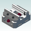
Version 1.0.0
306 downloads
Intended for the advanced Mastercam user, this book contains new projects demonstrating a variety of Advanced Multiaxis milling applications. The initial tutorials introduce Mastercam’s simplified multiaxis user interface featuring custom application toolpaths, and they later transition to the more advanced interface. Topics include Tool Box toolpaths such as Projection, Impeller floor surface and Impeller blade swarf finish toolpaths. From the Wireframe toolpath family, you will learn how to use Parallel to multiple curves and Morph between two curves. You will also generate rough and finish toolpaths from the Surface/Solid toolpath family, such as Morph between two surfaces, Parallel cuts, Swarf milling and Parallel to surface. Additionally, a special project is designed specifically to familiarize you with different Collision control strategies and how to verify the toolpaths using the new machine simulation module that combines toolpath backplot mode and material removal mode with collision detections.Free1 point -
We tried them here a couple of times. Metal removal rates were fantastic, but tool life was about 2 minutes. You need to break your toolpaths into 120 second segments, have 5 or 6 identical cutter bodies set up, a squad of low rent helpers changing inserts, and a Bill Gates sized bank account. To make matters worse, the swarf is a fine abrasive dust that will destroy a machine tool in short order. I know there are shops using ceramics successfully, but I have no idea how they are doing it.1 point
-
Any new tips/tricks/basics? I'm VERY green on this 3d stuff and am having problems with my customer's cad files (IGES from Pro-E). I can manipulate the file to the right orientation, but can't find any endpoints or entities ...it's all surfaces. Can I make toolpaths from just these surfaces?? Do you always have to "contain" your toolpath? How do I make arcs & lines fom my file that is all surfaces? Will try above suggestions also. Thanks! Steve1 point
-
I installed a DVF5000 in Buffalo just before COVID. We got the machine all dialed in and I asked him if he bought tool holders. He pointed to a shallow box on a pallet nearby and I see about 200 holders from god knows how long ago thrown in helter skelter. Fretted, dinged, old collet holders, side lock holders from the 80's. I cried but kept my mouth shut.0 points
-
Then there is G05 P10000 but who keeps track?0 points
-
That is a fillet where the angular arms meet the horizontal surface.0 points
-
Good Lord, that was an intense 10th grade machine shop class.0 points
-
Tell him to go back to school and learn how to design something that is manufactureable. What is the max radius allowed in the corners? Had a company years ago ask the place I was working for to machine some rails for a robot system. They were 40 feet long and they wanted us to hold .001" tolerance for flatness, positions and other things on these rails. I told them $1,000,000 per rail there were 12 of them and it would be a 48month lead time and still could not say we could hit those tolerances. Engineer was not happy left and went to 40 different shops and every single one of them no bid the project. The owner came along the 2nd time he came in and wanted to understand why we wanted so much, but also why where the only ones willing to even bid the work that everyone else called impossible. I told him it was impossible in 6061-T6 aluminum to even think about trying to hold that kind of a tolerance. I then had to teach them both the engineering 101 stuff about how temperatures and other environmental factors make even checking the part almost impossible. They both looked at me like didn't think about that. I then asked then what is the systems form, fit and function? Once that was said and done I showed them and extrusion that came in 10' lengths that with some holes added to it would do everything they needed. The extrusions were about $120 each. Machining the holes would be about $200 for each one and they could do everything they needed for the system with a +/-.100" tolerance over the 40 feet.0 points


.thumb.gif.b2f8d84f284177ecd2bf348424895690.gif)


