Leaderboard


Popular Content
Showing content with the highest reputation on 04/05/2021 in all areas
-
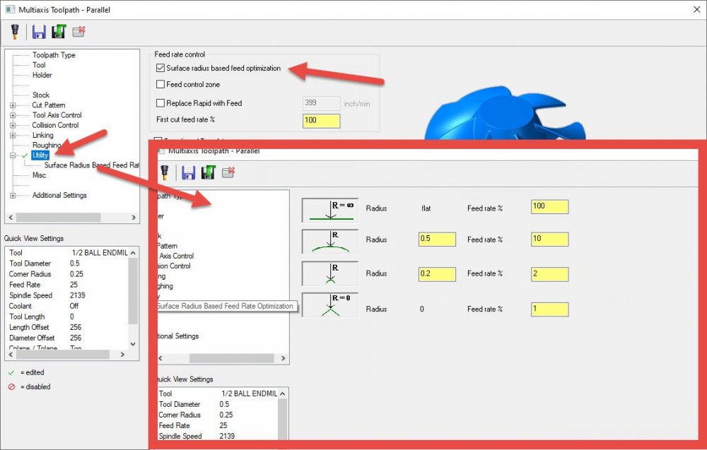
For those seeing this that work in the multiaxis world, there's an entire options page for surface radius based feedrate adjustment to achieve similar results:
 4 points
 -
2 points
-
you could try a 3d blend toolpath, that may do a fine job1 point
-
You just enter the maximum you want it to decrease or increase, so you dont need to worry about the % if you use the inch value to the right of the % field. Like if im running at 10ipm and i don't want it going any slower than 5ipm in corners than my min feed would be 5ipm, the software will use an industry standard formula to adjust the feed while never leaving your min/max feed rate range applied on that page. so you can use whatever % you want but the way i wrap my head around those fields is what is the slowest and fastest i ever want the tool to go, its going to use an formula no matter what, your just setting the slowest and fastest its able to go when making feed rate adjustments. i hope that makes sense1 point
-
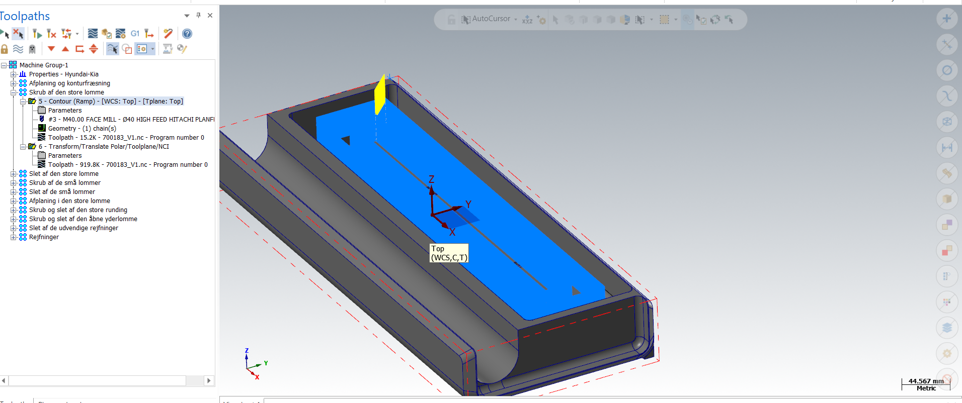
In cases like this I will create a flat surface above, run a flowline on that, then project that toolpath down onto the surfaces I need to cut...1 point
-
Get a Citizen with LFV (low frequency vibration). It breaks chips on every rotation.1 point
-
Thanks for the help! I managed to get it done by creating a toolpath that with 2 muliti passes went down 0.25 mm in Z, then copying it all the way down in the pocket. 10 min roughing time of a 500 (L)*113 (W) *30 (D) mm pocket.
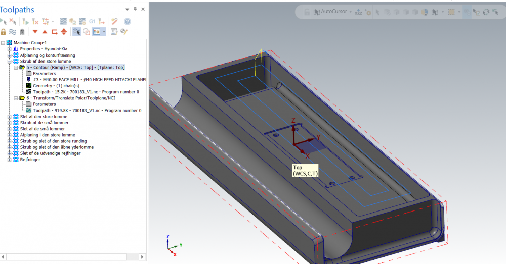
 1 point
 -
In this box you just allow maximum decrease feed. You can type 99% decrease of your cutting feed, Mastercam will calculate it by formula. I don't really know which formula they use, it could be same as per Sandvik book or the formula that shows in video HAAS Tip of the day:1 point
-
You are spoiled youngster Back in the day, even simple stl's were 2 or 300 meg. I once tried to turn a 350 meg stl file of a roughed impeller into an IGES file using Vericut. It was very very slow, so I left it running and went home for the weekend. On Monday, my PC was a brick. The IGES file had gotten so big it ate my hard drive and crashed the PC. Coming from a background like that, I find the stuff they do with STL's today amazing. I used to have to verify just one vane of my impellers like a piece of pie, and even that brought my PC to it's knees.1 point
-
I think the guys will take a 30 meg stl file saved out of a Verify session, try to turn it into a solid and crash their computer1 point
-
CONGRATS ! I too have recently entered the fifth axis world , and I would have agree that it is kind of tough , especially when you have no training or help . So glad to have this forum to turn to when I get stumped , there are a lot of smart people here.1 point
-
Consider Milling where possible. Use the "Chip Break" option in the Mastercam Toolpath itself. For "longer" sections, consider using a Part-Off Tool or Groove Tool, to machine several grooves, say 0.500 between the grooves. Then rough with a Turning Tool, and the cuts are now interrupted, creating shorter chips. As Matt mentioned; program heavier FPR (Feed-per-Revolution) values, to actually force the chip to break.1 point
-
Use chip-breaker inserts and take a heavier cut?1 point
-
Hey! I resemble that remark0 points
-
There are a few cool instances with 2022 where I've found myself turning my surfaces into a mesh to do the model edits I want, rather than desiring the other way around. The smoothing and refinement possible on organic shapes is amazing. Specifically, I had one scenario where scanned intake port data for reverse engineering, and resultant wireframe cross sections, were resulting in some ripples in the NURBS surface that was swept through them. Send it out to mesh, use smoothing commands to remove ripples, path directly on the mesh, and done. Much simpler than syncing nodes and tweaking sectioned wireframe loops to try and smooth surface propogation. I finally gave up and swapped my musclecar carb to EFI a few years ago after getting tired of cleaning the bowls and jets of ethanol jelly every spring and then chasing idle and mixture adjustments from spring to fall. The future is now, old man!0 points
-
Oh man, now I'm jealous. Actually, it won't be too bad here in MA for the next 9 months or so. But I sure do miss being someplace warm every January/February...0 points