Leaderboard


Popular Content
Showing content with the highest reputation on 05/08/2021 in all areas
-
ViewManager.ConvertToViewCoordinates only appears to map the point; it doesn't seem to include the origin. Below is a short example showing how to take the shift into account. using Mastercam.App; using Mastercam.App.Types; using Mastercam.IO; using Mastercam.IO.Types; using Mastercam.Math; using Mastercam.Database; namespace pointMappingExample { public class Main : NetHook3App { public override MCamReturn Run(int param) { var selectedPoint = new Point3D(0, 0, 1); SelectionManager.AskForPoint("Select a point", PointMask.Null, ref selectedPoint); PromptManager.WriteString("Select the source view"); var sourceView = ViewManager.SelectFromPlaneList(); PromptManager.WriteString("Select the destination view"); var destinationView = ViewManager.SelectFromPlaneList(); PromptManager.Clear(); var pointService = new PointService(); var convertedPoint = pointService.ConvertToViewCoordinates(selectedPoint, destinationView); var transformedPoint = pointService.TransformToViewCoordinates(selectedPoint, sourceView, destinationView); DialogManager.OK($"Selected point(world)\n" + $" X:{selectedPoint.x}\n" + $" Y:{selectedPoint.y}\n" + $" Z:{selectedPoint.z}" + $"\n" + $"Converted point({destinationView.ViewName})\n" + $" X:{convertedPoint.x}\n" + $" Y:{convertedPoint.y}\n" + $" Z:{convertedPoint.z}" + $"\n" + $"Transformed point({destinationView.ViewName})\n" + $" X:{transformedPoint.x}\n" + $" Y:{transformedPoint.y}\n" + $" Z:{transformedPoint.z}", $"Results"); return MCamReturn.NoErrors; } } public class PointService { //Short method public Point3D ConvertToViewCoordinates(Point3D point, MCView destinationView) { var destinationViewMappedOrigin = destinationView.ViewMatrix.MapPoint(destinationView.ViewOrigin); return ViewManager.ConvertToViewCoordinates(point, destinationView) - destinationViewMappedOrigin; } //Long method public Point3D TransformToViewCoordinates(Point3D point, MCView sourceView, MCView destinationView) { var sourceViewMappedOrigin = sourceView.ViewMatrix.MapPoint(sourceView.ViewOrigin); var pointInSource = sourceView.ViewMatrix.MapPoint(point) - sourceViewMappedOrigin; var pointInTranspose = sourceView.ViewMatrix.GetTranspose().MapPoint(pointInSource) + sourceView.ViewOrigin; var destinationViewMappedOrigin = destinationView.ViewMatrix.MapPoint(destinationView.ViewOrigin); var pointInDestination = destinationView.ViewMatrix.MapPoint(pointInTranspose) - destinationViewMappedOrigin; return pointInDestination; } } public static class Matrix3DExtensions { public static Matrix3D GetTranspose(this Matrix3D m) { var rowOne = new Point3D(m.Row1.x, m.Row2.x, m.Row3.x); var rowtwo = new Point3D(m.Row1.y, m.Row2.y, m.Row3.y); var rowthree = new Point3D(m.Row1.z, m.Row2.z, m.Row3.z); return new Matrix3D(rowOne, rowtwo, rowthree); } public static Point3D MapPoint(this Matrix3D m, Point3D p) { var mappedX = (p.x * m.Row1.x) + (p.y * m.Row1.y) + (p.z * m.Row1.z); var mappedY = (p.x * m.Row2.x) + (p.y * m.Row2.y) + (p.z * m.Row2.z); var mappedZ = (p.x * m.Row3.x) + (p.y * m.Row3.y) + (p.z * m.Row3.z); return new Point3D(mappedX, mappedY, mappedZ); } } }1 point
-
Nah, RCTF does a calculation that increases the feed based on the desired chipload and stepover. It assumes your chipload is at 50%, if you specify a stepover smaller it will increase the resulting feedrate to maintain this chip thickness. What I would like to see is a feedrate that adjusts during the toolpath based on the peripheral of the tool, not centerline.1 point
-
I think you’ll need to map the point yourself if it’s not in world coordinates to begin with. Try multiplying the point through the transpose/inverse (They are the same in a unitized, orthogonal DCM) of the source view’s DCM (matrix), then multiply that point through the destination matrix. With this method you can convert a point in any view to any other view; the source point doesn’t need to be in world coordinates. Side note; you’re typing too much. Add some using directives so you don’t need to type out the namespaces.1 point
-
Its very important to adjust your feed rate when doing thread milling Factory feeds and speeds are driving the c/l of the tool and that can be 2 or 300% too fast when you are threadmilling with a tool near the finished size1 point
-
Here's a Reducing peck cycle... Designed for a 16 control. So with some mods, you could adapt it for a 15. In the last 15 years I've only put my hands on a 15 Control 1x.... so it's been a while. HTH % O9004(REDUCING PECK MACRO) (THIS PROGRAM IS DESIGNED TO RUN FROM A PRE-DRILLED HOLE) (USED FOR A DEEP HOLE WHERE TWO DIFFERENT DRILL LENGTHS ARE NEEDED) (USED WITH G184 CUSTOM MACRO CANNED CYCLE) (EX. G184Z-9.65R.01F6.I.3J.5Q.1E-6.3) (#18 "R" RAPID PLANE) (#4 "I" 1ST PECK) (#17 "Q" MINIMUM PECK) (#26 "Z" FINAL DEPTH) (#5 "J" REDUCTION MULTIPLIER) (#9 "F" FEEDRATE) (#3 "C" PECK RETRACT COUNT) (#100 INITIAL PLANE STORAGE) (#101 REMAINING DISTANCE CHECK) (#102 "Z" TARGET VALUE) (#103 "Z" FEED/RAPID VALUE) (#8 "E" SUB RAPID PLANE) #10=#4 (ERROR CHECKS) IF[#3EQ#0]GOTO5 #3=FIX[#3] GOTO6 N5#3=1 N6IF[#26EQ#0]GOTO50 IF[#18EQ#0]GOTO51 IF[#9EQ#0]GOTO52 IF[#4EQ#0]GOTO53 IF[#18LT#26]GOTO54 IF[#5NE#0]GOTO7 #5=1 N7IF[#5GT1]GOTO55 IF[#17GE.2]GOTO8 #17=.2 N8#100=#5003(STORE CURRENT Z POSITION) G0Z#18(RAPID TO R PLANE) #101=ABS[#5003-#26](CHECK FOR REMAINING DISTANCE #101=FINAL DEPTH) #103=#18(SET 103 TO R PLANE, #103=NEW "R" IN PART) WHILE[#101GT[#4+.02]]DO1(TEST 101 FOR FINAL DEPTH) #149=0 WHILE[#3NE#149]DO2(CHECK FOR RETURN TO "R") G0Z#103(RAPID INTO NEW "R" PLANE) IF[#101LE[#4+.02]]GOTO2 #103=[#5003-#4](NEW DEPTH) G1Z#103F#9(FEED TO "Z") #101=ABS[#5003-#26](RECALIBRATE DISTANCE TO GO) #103=#103+.1(RETURN PECK IN "R" PLANE) G0Z#103(RAPID TO NEW "R") #4=[#4*#5](RECALCULATE FEED DISTANCE) #149=#149+1(INCREMENT COUNTER) IF[#4GT#17]GOTO1(CHECK FOR MINIMUM PECK) #4=#17(SET TO MINIMUM PECK) N1END2 G0Z#18(RAPID TO ORIGIONAL "R" PLANE) END1 G0Z#103(RAPID TO PECK RETURN PLANE) N2G1Z#26(FEED TO FINAL Z) GOZ#18 N3G0Z#100 #4=#10 GOTO4 (ERROR STATEMENTS) N50#3000=1(NO VALUE IN Z) N51#3000=2(NO VALUE IN R) N52#3000=3(NO VALUE IN F) N53#3000=4(NO VALUE IN I) N54#3000=5(R IS DEEPER THAN Z) N55#3000=6(J VALUE MUST BE LE 1.) N4M99 %1 point
-
Found the problem. The backplot axis is wrong on the Tool Axis Control. Change it to Z from X and the file is good to go. 2021 file with fix
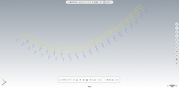 1 point