Leaderboard


Popular Content
Showing content with the highest reputation on 06/01/2021 in all areas
-
It's an MP Systems AT RF.3 points
-
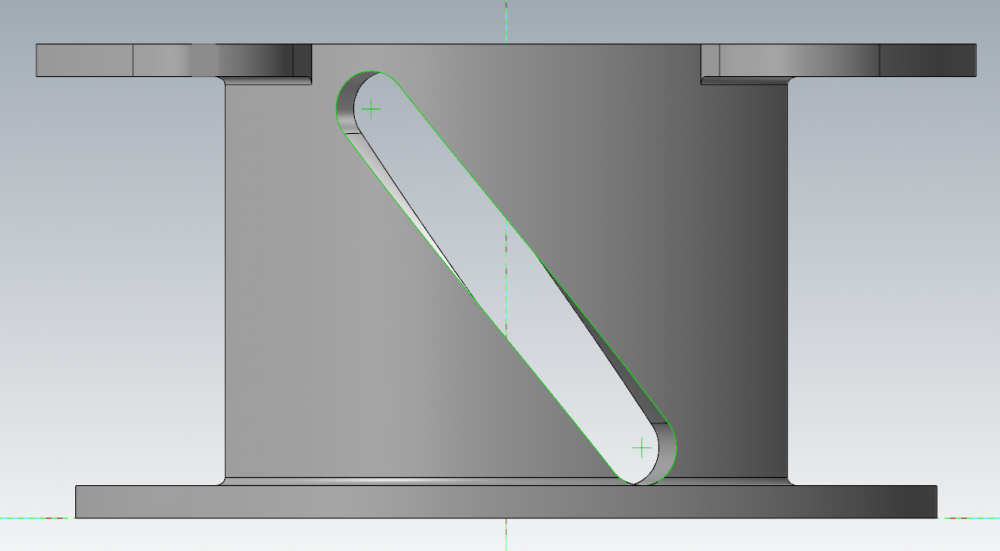
Wireframe -> Bounding Box -> Center Point?3 points
-
It seems like a good system, our subprogram for turning the TSC on and off was just missing a couple G103s.2 points
-
Try this.
 2 points
 -
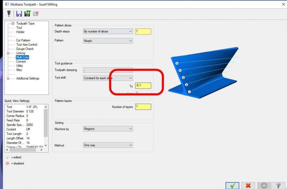
In your Swarf toolpath, go to the "Collision Control" setting page. Set to Lower Rail and in the Distance Above Lower Rail setting, use a negative number of your choosing. Paul2 points
-
By the way, I'll be doing a YouTube Live session this weekend on how to edit the Custom Drill Cycles, to add support for Renishaw Probing, to the MPMaster Post. This will be an opportunity to learn and ask other Post Questions as well. Try searching "MP 101" or "MP 301" on YouTube, and subscribe to my channel so you can get notifications.2 points
-
You guys rock. Precisely the info I was after, and I hope it will be of assistance to others as well!1 point
-
One thing I've found working with 5X toolpaths If you have MachineSim, use it. I have a home made machine sim for our Okuma MU. It does a very good job of showing stuttering bouncy 5X toolpaths. In fact it does a better job of showing toolpath instability than Vericut does. If machine sim shows a toolpath is performing poorly, it will perform poorly on the machine even if backplot and Vericut run smoothly.1 point
-
It's been so long I don't honestly remember. But what I do remember is when using 5x Curve. Filter setting, and tool axis control have more importance on the smoothness of the path than the curve following method itself. Of course the curve following method will influence the "resolution" of the tool axis control and overall motion of the machine, but the "smoothness" of the tool axis control is more dictated by the method of which you pick. Way too many ways to skin the cat once you get into 5x Curve to take a guess on what you should/could be doing.... Post up or send me an example of what you are trying to do, and I will see what I can do to make it "smooth". I'm sure Ron or James would love to pitch in as well. More generic the better as all can learn if we make it public. When I think of making a smooth 5x toolpath, my brain immediately starts thinking in terms of physics and calculus. Determine the outcome desired, then balance that with the cutting velocity required, then you can think in terms of acceleration in XYZ, and then in the case of acceleration of the rotary axes, which IMHO will slow things down more than accel/decel issues in straight XYZ, as they affect the XYZ motion directly NO MATTER WHAT, further from center ->> the worse it gets. This is where options like the smooth TCP / posture control function on a Fanuc control actually smooth out the angular displacement issues between points which cause great acceleration changes in the rotary and translational axes. If you don't have those options, you have to do that at the toolpath level, which can be done with time, patience, and knowing how to recognize and eliminate the trouble spots. This is typically the way to get the absolutely fastest path anyway, so for long run stuff you may as well start to develop your process on doing it. Food for thought: if you have a generic non-tcp post, posted from centerline(s) of rotation, you can edit the post to actually calculate and output acceleration values for each axis at each point and you can theoretically use that code to look for your hot spots mathematically, and then subsequently know where you will have areas on the machine that will greatly slow it down. I haven't done it yet, but I think there is a function on the post side of things that you can use to draw geometry on a level in mastercam. You could in theory use that to draw a visual representation of the toolpath that met certain criterial for acceleration, so you could visually pinpoint the trouble spots. Many times it is just a matter of tweaking a few vectors, or deleting a point here and there. I have written filters in excel that filter the NCI, I then import NCI and post the paths. Sometimes resulting in 50% or greater reduction in cycle time, with vastly improved surface finish due to constant cutting velocity. blabber blabber blabber, I could go on forever. I'll stop now, before I dig a big hole where I need to explain myself.1 point
-
Awesome! I thought I had missed it. Thank you so very much for these sessions! I don't always get to watch them live, but I always watch them and I always learn something new.1 point
-
I got caught up with exploring a new feature in Mastercam; the ability to add Custom Bitmap Graphics to a Drill Cycle. So I ended up building Graphics for Protected Positioning P9810, XYZ Single Point O9811, Web/Pocket O9812, Bore/Boss O9814, B-Axis Align O9817/O9818, and Stock Allowance O9820. I'll do the Live session this coming weekend, to give people a chance to prepare. I'll post the Date/Time soon.1 point
-
we ballbar our routers. not wood working tho, we are a composite shop. most routers are production trim mine is used mostly for tooling. it would not have been a route i would have initiated (10k investment) and it just tells you info on servo tuning and squareness, some other data as well. some one else pulled the trigger on ballbar purchase before i had chance to give input. now we have it so i use it. I could simply do a circle triangle square test and or manual tram sweeps etc. to accomplish similar info. we are not splitting hairs with our router just not designed for such.1 point
-
Compare the price of the equipment for the size and accuracy and then you will answer your own question. 5 Axis Routers for a 4' x 4' x 10' machining envelope is around $125k a Metal machine with the same size is about 10 times the cost. You get what you pay for.1 point
-
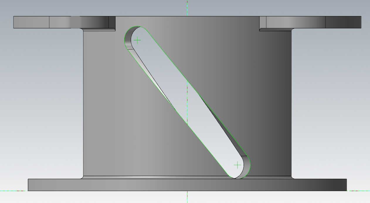
Well seems that Solid Sweep has gone through some changes and not working like it used to when I first started using it 20+ years ago. I would have done it exactly like you did using that print. Part passed inspection and customer is happy then life is good. I can create the solid shape using the start and end chains as shapes drawn in holes at the correct place. I rolled the geometry using splines to give me good sides to work from verse the lines. If you made the toolpath from the splines your toolpath would have been smoother that just using the lines also. Here is a link to my file and I got something that looks okay, but still wonky in my opinion. Link
 1 point
 -
Better get on the phone with FANUC then.1 point
-
It's because they are splines1 point