Leaderboard


Popular Content
Showing content with the highest reputation on 03/17/2022 in all areas
-
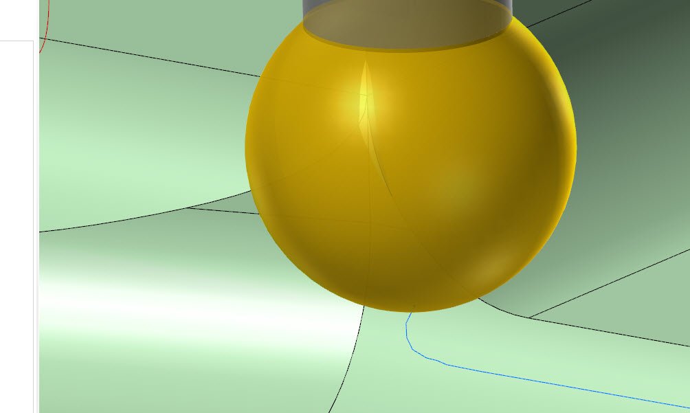
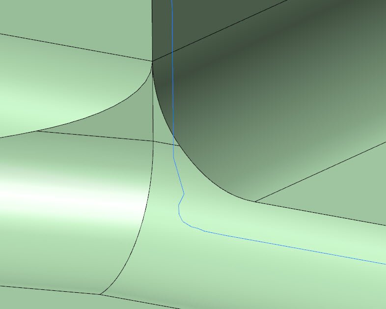
Hey Jake, thanks for uploading the file. This "noise" issue is something we spent some time addressing for 2023 to improve results. This is happening specifically in the area where those two sharp edges come together to the single edge- What happens when the lollipop transitions through that "Y" is that at some point, we need to shuffle the tool to the side so as to not violate/gouge our part beyond our allowed edge break and tolerance. 2023 handles this a lot better and gets rid of the funky oscillation. It actually helps to loosen the tolerance back up again, so as to allow more wiggle room for the tool to overcut/gouge as it reaches those intersecting surfaces. I brought it up to 0.002" on your path and regenerated. The remaining zig you see below is the minimum necessary move to avoid chewing up the adjacent edge as we pass through the Y intersection: And here's what it looks like for tool engagement in backplot:
 3 points
 -
Okay that worked great I just had to make a small mod to the curve if you look from the top it did not match the original 2d drawing but it was just a matter of moving the front cut profile to the left 0.15mm so the profile intersected the first edge curve then cut the solid with the new profile and create a new edge curve. again thank you very much I have learnt so much more just from you'r short very well done video Mud Guard-V2.mcam2 points
-
This does happen from time to time. Do you have solids/surfaces displayed when doing this? Try just wireframe. I generally find that I need to restart my PC when this starts to happen.2 points
-
Emuge has small high feed mills. They gave me a 1MM high feed mill. I looked at it under a microscope and sure enough. I thought they were crazy. I ran it in 304 stainless at a .004" DOC and 80 IPM. Cut beautifully.2 points
-
Touch off the tool and add whatever the the pilot length is. This will help avoid any potential mishaps like having your retract or clearance height being too low.1 point
-
Hey Jake, Even though we're locking this to 3 axis, Deburr is still a multiaxis path in the background, whose output is restricted to linear segments- so there's no way to have this path type output arcs. Depending on your machine, you should try going after smoothing/tolerance parameters at the control to loosen them up and allow the machine to flow through these linear segments more naturally- IE, Haas G187, Heidenhain Cycle 32, etc. Using a looser toolpath tolerance to avoid dense clumps of points will also help. That 0.0005" tolerance on your example path inserts some pretty clustered groupings that would wreak havoc on machines with no/limited smoothing and lookahead.1 point
-
I made a quick video showing the idea. https://www.dropbox.com/s/m2ty2t8z3heezvo/Trim To Surface.mp4?dl=01 point
-
That's definitely an option I'll keep in mind. It won't work for the particular project I'm on, but I'm sure I will run into this issue again. Thank you.1 point
-
Sorry guys, I lied, (mistaken). It was a 2MM High Feed Endmill. Paul1 point
-
In a case like this where there are blending issues I'll try to use a smaller tool to reduce the effect that Dylan pointed out above. It doesn't completely solve the issue but it does make enough of a difference to improve the toolpaths overall finish. I changed your tool from a 1/4" to a 3/16" lollipop and I think it made a noticeable difference on that particular corner. I know that may not be an option depending on what tools you have in stock but if so its worth a shot. Deburr_Toolpath .187 lollipop.mcam1 point
-
All the time nature of the work I am normally doing. When it gets up to 10 seconds then I shut it down fire it back up and get back to the 2-3 second wait on the bigger files. 1 gig with 400-1000 operations is my normal file size. Did some some 50 and 70 operations files in the last week and that was nice to not have to watch paint dry all the time when programming.1 point
-
You can try to make a surface and trim your solid to the surface. Your surface will need to extend past the solid. Possibly a Swept surface along 2 rails.1 point
-
thanks sir. got it.1 point
-
I never ever use arcs to drive threadmill (or circle mill for that matter) as it has scrapped parts in the past and I have lost all faith in it. I only use points and I set the diameter myself in the toolpath to what I want. I have helped so many programmers with this when they select a solid edge for 40 holes then select that one arc thats .01" bigger and wonder why its blown out.1 point
-
Communities > 3rd Party Developers > Post Processor Resources > Mastercam 2022 MP Reference1 point
-
OK then... Once you loging go to1 point
-
Probably magnetic vortex coupled with the moons current cycle plus position of mars. Try again at a full moon and all should be good. HTH!1 point
-
Something I see all the time is people "reusing" Tooling Component Solids in their Mastercam Files. They Import, Move, and Save those models, and then continually move/copy/rotate these models. All Solid Models (even those without "operation history"), keep track of the transformations "behind the scenes". After you import Solid Geometry into your Mastercam File, (Especially when using Merge), use the "No History" command, on all your solid bodies, after you've moved them into position. I also like to run "Optimize" on all solid geometry that I've imported into Mastercam. You'd be surprised how much "overhead data" you can eliminate by using these two functions. For Fixture Plates, Etc., I like to get rid of any extra holes/features, whenever possible. I will typically keep a "featured" model on a separate level, but then will go and "Remove Features" on models which I'm bringing into Verify or Machine Simulation. You want the "outside skin" of vises, fixtures, riser blocks, etc., but having an "internally modeled feature" just creates more computational overhead. This is probably not related to your specific issue, but removing Solid History can really help streamline your files, and get rid of computational bloat.1 point
-
There are hard lessons to learn in setting a datum below a part highest point. There are as many ways to accomplish a part as there are stars in the sky. In the end, you want something that runs in a reasonable time, produces a good part and is easily understandable by anyone that may be looking at your processes. That's why you see the suggestions on tool holders, adding notes in operation fields etc. etc. The more diligent and obsessive you are with this, the more successful you will be. Learn good habits now so you don't have to retrain yourself later.1 point
-
We run our HSS jobber drills at 350 SFM starting at 1/8", solid carbide drills at 850 SFM starting at 7/32" and 409 SFM starting at No.36 coolant thru drill and up to 590 SFM at 1/2" in aluminum.1 point