Leaderboard


.thumb.jpg.e1ed32e8dc33a68b1f20806bb5d55e08.jpg)
Popular Content
Showing content with the highest reputation on 08/01/2022 in all areas
-
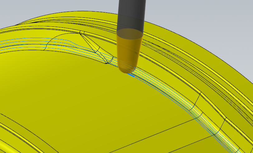
I put this on in less than 5 minutes, but I have a LITTLE BIT of seat time on Unified :) If you're still on 2021 or 2020, you can use Morph set to Curves for the same effect. if you get weird/inconsistent gaps, under advanced parameters set it to "exact." I just chained the bottom of the fillet and the top of the wall (under the undercut) w/ a 6° tapered 6MM ball mill: Tool axis control is set to rotate around the Z, but keep the tool 87° off of the surface normal so it will sort of swarf, but then I turned on collision control to have it automatically tilt if it'll gouge, so it's not really "tied" to the surface if it has to jiggle to get around those weird bumps. It would be equally easy (but more time consuming for selection) to have done the whole thing, but I wanted to keep the file size down and get you going. Feel free to reach out if you need more help! 1736119534_10333228_A_1-INNERMIDDLEHOUSING_ROUGH_STEP.zip
 2 points
 -
If that's beryllium copper mask and coveralls up. That's some nasty stuff. You may also have a hard time getting rid of the coolant if it becomes known what you were machining. We no longer machine that crap. The speeds, feeds and depth of cut will need to be slowed down also.1 point
-
So what I am finding with power mill is that it is definitely an engineers delight and would be helpful having that background. However for the average shop toolmaker machinist type person it’s really quite overwhelming unless heavy training in the works! It has an unbelievable amount of menus selection to accomplish very simple toolpathing. Trick is., which one of those hundreds of selections works when they need a program yesterday I just had a dozen or so printed tutorials which leave you with dozens of questions. My assessment for the present is to acquire Mastercam to get stuff moving than continue with power mill when time for extensive training opens up! They have agreed.1 point
-
I get this issue too on some 3D toolpaths. Update 1 did not fix it. You have to Disable GPU processing in config under Simulation. At least, that's the only thing that worked for me.1 point
-
If they come in to check on the status of the project I might try to broach the subject. It's cast prototype though...I'm unsure how much thought or care goes into some of these details. We've got a bunch of exceptions for the interior features of the part, too. Granted, we can tip to make a lot of it work but you're basically looking at having to run a .250 ball EM with ~13" of stickout to make the interior of the part the way it was designed. Luckily we got clearance for .250 rads all the way around. Either way though, you guys know how it is, it's just so much more difficult to make clean paths off of geometry that's no good or nonexistent.1 point
-
The biggest question I 'might" look to answer....does the model the engineer created, truly confer the design intent or was there a hope that the machines would give them what they want... The biggest reason I would ask is simply how bad that geometry is....it makes me think someone just didn't know how to get what they really wanted out of the software and into the model.1 point
-
I just got off the phone with tech support. It's a known issue with 2023 they said. There's an update I'm about to download that supposed to fix the issue. If you run one setup then click the down arrow next to verify selected operations and click add to current verification, the tool doesn't crash through the part. Thank you, I've only been using Mastercam for a couple years and just started using it again recently. I still have a lot to learn...1 point
-
WCS for each side? If so they need to be run for each WCS not complete in Verification.1 point
-
That is nasty any way you look at it. Whoever modeled that doesn't understand the first thing about manufacturing. That will take some work and don't think swarf will be you friend here. I think you are going to have to surface machine those walls with a 4mm ball endmill since the root radius is 2mm. The floors with a bull endmill with a 2mm radius, but at each V raise with the sharp corners someone would be getting a 2mm radius in the bottom corners. You can swarf large sections, but the whole thing not going to happen. Swarf will not handle that.1 point
-
I've done a bunch of parts like that. Usually with full radius keyway cutters or lollipop tools... depending on how much negative it goes. You have to turn off gouge checking.1 point
-
If you purchased the post the company that wrote the post should have a backup copy of the post. If you know who your purchased the post from you should be able to reach out and get your copy back. You could try mpmaster there is a HMC machine def included in the files. If you try that post WCS should equal TOP and tool/Cplane would be FRONT, RIGHT, BACK or LEFT for the primary planes.1 point
-
Is the material round stock or rectangular? If it's round it more than likely 145 material and that cuts nicely. If it's rectangular it's more than likely 110 material and that loves to hold stress so you will need to take lighter cuts. The part looks rather stable though.1 point
-
Thanks for the suggestions! I was leaning towards the Mitsubishi WSX actually, but a higher up ordered a Seco Quattromill for me since we already stock inserts in our toolcrib. It just arrived this morning and I did a test cut in a scrap piece of 4140. On a part that is 6"x6"x2" held in a raptor dovetail fixture and running the cutter at 600SFM and .003FPT with air blast I was able to achieve a flatness of .0002" or better when checked on the plate and 3 points. The finish is a little smeary probably due to the shallow DOC but it checks as a 15microInchRA so I think I am relatively satisfied. I will be finishing the big 15"x15" plates later this week and we will see if the flatness error gets magnified at those distances. I assume they will1 point
-
David - that worked perfect....thanks again if rotary_type$ = 3, "add g-code here that I wanted...", e$1 point
-
I'm off for the night here but i'm pretty sure there is a post variable for this setting. You should find it easily in post documentation. It's 'rotary_type$' with values 0 to 3. It's well explained in post documentation with Mastercam screenshots.1 point
-
What I've always told people is that on a 5 axis toolpath, I have 50% confidence it'll run right on the machine from backplot, 75% from Machsim without being tied to your post, and 95% with it being tied to your post. To get 100% you need to have a trusted verification software like Camplete/Vericut/NCsimul/etc. What JParis is trying to say is that you have two sets of code being run here. Mastercam toolpaths are stored in a "generic" format called NCI. When you hit the Post button, it runs through your machine's post processor that contains all the information it needs to say "Your machine has a B axis rotating head, so I'm going to adjust the X & Z every time the B angle changes," etc. It's then converted this way into the G code you produce. In order for MachSim to translate any sort of movement, it also has to have its own post processor (called Multi-X post). The problem is that, depending on your machine, your post and MultiX post may arrive at completely different solutions to solve the position; E.g., Machsim goes to A+90, which clears the fixture. Your post chooses to rotate to A-270 which will not clear the fixture. You have no way of knowing that it did that until you run it on your real machine! There's an option available from post builders like Postability and In-House Solutions that hook up the Machisim model to your post, so instead of using the Multi-X post, it uses your post to resolve all of the positions. It won't help with custom M codes and such, but at least all of your positions will be the same as they post out.1 point
-
Yes, it is certainly possible to add functionality from one Post, to another. You do need to know the architecture of the Post, as you generally can't just "copy and paste" Post Block Sections, because you need to know if there are variables which are shared across the original post and new "code sections" you're adding. Also, variables must be initialized and/or formatted, so there are often additional sections which must be copied, to support either Post Blocks, or sections of code being added to existing blocks.1 point