


machineimpossible
-
Posts
38 -
Joined
-
Last visited
Content Type
Profiles
Forums
Downloads
Store
eMastercam Wiki
Blogs
Gallery
Events
Everything posted by machineimpossible
-
tool assembly projection dimensions setup sheet
machineimpossible posted a topic in Industrial Forum
Is there any way to have the small image on the MILL 2 setup sheet show the projection amounts of all the assembly components of a tool? tool in the first picture was built in the stand-alone tool manager with assembly components in the assembly builder. When you look at the "holder" section of the toolpath parameters, it shows the projection amount for each component of the tool assembly. But when I output the setup sheet report (based off of MILL 2) I get the image in the second picture.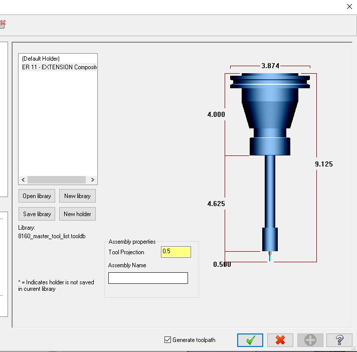

-
As I understand it, these registers can be setup to output modifications to cut condition codes (feed rate, on/off, MAO, etc) per each pass or even on specific lines of code using toolpath editor? How can I setup these registers and how do I call them in the post? Thanks
-
Found it, thank you. That worked.
-
Using MP Master with 5/30/19 last revision note. When I post a toolpath, or group of toolpaths that are all on B0. and do not have any other index positions, I do not get a B0. output. I have found some older forum posts recommending: #sav_rot_on_x = rot_on_x #Uncomment this line to output rotary axis value even when it's not used <--------uncomment this line but I cannot find anything like this line in the post?
-
I'm trying to use this, but am not sure where to put it, and where to put the call for it. Thanks
-
Gnomons on bookmarked viewsheets image capture
machineimpossible replied to machineimpossible's topic in Industrial Forum
One simple work around is to move all your geometry far away from the system origin and use all user-created WCS/t/c planes. That way even though those system gnomons are still showing up in the screen shots but just can't be seen. -
Gnomons on bookmarked viewsheets image capture
machineimpossible replied to machineimpossible's topic in Industrial Forum
What's odd is that it is only showing up on certain views, and seems to only be happening with bookmarked viewsheets. If I do normal screen captures without the viewsheets function, then I don't get any of those Gnomons. -
Gnomons on bookmarked viewsheets image capture
machineimpossible replied to machineimpossible's topic in Industrial Forum
Here is an example setup sheet, with the Gnomons. I have all display settings for Gnomons off in MC that I know of. I cannot figure out where these are coming from. TEST 2.pdf -
Gnomons on bookmarked viewsheets image capture
machineimpossible replied to machineimpossible's topic in Industrial Forum
it shows up in both the setup sheet and the MC graphics window. Although, when I close/re-open the MC file, they will be gone from the graphics window. If you see my screen shot above, that is an example of what I am getting in the setup sheet. The Gnomon on the right is the T/C Plane, which I want. The one on the left is what is happening somehow in the image capture during setup sheet creation. The other strange thing is that they are not showing up on every image capture, but it seems to alternate every other capture. In this case I have the main graphics window capture and 3 view sheet captures. And what is weird is that when I post the setup sheet again, it seems to "switch" to the other set of captures? -
Gnomons on bookmarked viewsheets image capture
machineimpossible replied to machineimpossible's topic in Industrial Forum
I don't see anything when I do that search. -
Gnomons on bookmarked viewsheets image capture
machineimpossible replied to machineimpossible's topic in Industrial Forum
I am not sure abut Verisurf, could you send a screen shot of where I need to look for that? -
Gnomons on bookmarked viewsheets image capture
machineimpossible replied to machineimpossible's topic in Industrial Forum
I turned off Gnomon display completely and I'm still getting those random ones showing up. -
When I use book marked viewsheets for image captures for setup sheets, I get these Gnomons that seem to be from the original world Top graphics gnomon. They appear along with the T/C Plane Gnomons on the image capture, which is not what I want. I want to only see the T/C Plane gnomon. Is there any way to turn this other gnomon off?

-
Setup sheet linked to Viewsheets?
machineimpossible replied to machineimpossible's topic in Industrial Forum
I see how the bookmarked viewsheets can help make the screen captures easier. Now the issue I am having is adding the CAPTURE sub-report to setup sheet design in Active Reports. I can't seem to get it to work as it does in the standard Setup Sheet (MILL).rpx -
I'm am trying to add the -Setup Sheet (CAPTURE).rpx sub report to an existing Setup Sheet design, but cannot seem to get it to work. I looked at the Setup Sheet (MILL).rpx inside of Active reports designer as a guide. I thought I had put the sub report in the same place and all the same fields filled out, but when I go to post a setup sheet I just get a blank screen on the Active Report viewer. Thanks
-
Setup sheet linked to Viewsheets?
machineimpossible replied to machineimpossible's topic in Industrial Forum
I also seem to remember you could have a tiled graphics window of several viewsheets, or did they get rid of that? -
Setup sheet linked to Viewsheets?
machineimpossible replied to machineimpossible's topic in Industrial Forum
Do those images that you capture from the viewsheets remain stored in the setup report, such that if I close the file and open it up 6 months later and post a setup report, I don't need to recapture those images? -
I know the standard setup sheet outputs an image of your current graphics window when generating the report. Is it possible to have the setup sheet report do the same for all your current view sheets' graphic windows? I would like to have several established views and have the setup sheet report output an image for each one. Thanks
-
am I missing something with Machine Simulation and Verify? There seems to be no collision detection between tool HOLDER and fixture/machine (only holder and stock) ?
-
Modify Tool List output from Op tree manager
machineimpossible replied to machineimpossible's topic in Industrial Forum
Thank you. I was actually looking for the sub report file itself for where that tool list comes from. it is -Tool List (MILL-OPMGR).rpx I was able to find in the "MSC" folder: C:\Users\Public\Documents\Shared Mastercam 2020\common\reports\MSC -
I'm trying to change the tool list output you get from right clicking in the Op tree. I want to add to the report the Manufacturer tool code. I have done a little bit of report editing with Active reports Designer, but I can't seem to find the report or sub-report where this tool list is coming from?
-
So the inspection is being done right from the solid model as nominal. I cannot speak to any import/conversion issues with the CMM software bringing the model in. The format we were supplied from the customer was .STP but I don't know if that went right into the CMM software with no issue, or if it needed to be converted to something else. As to the method, they are using full scanning for everything, not just minimal points. so each of these internal arc features are scanned with dozens of points all along and across the feature. So I would say they are being checked as true partial cylinders, and the CMM is report deviations of Form, Position and Size to the solid model as nominal. Which of course is required to truly evaluate a profile of surface tolerance.
-
Machine Simulation missing collisions?
machineimpossible replied to machineimpossible's topic in Industrial Forum
Got it. Now would that be included under the umbrella of Post support maintenance? because we are up-to-date on that for this year. -
Machine Simulation missing collisions?
machineimpossible replied to machineimpossible's topic in Industrial Forum
Now my next question, as others have added, your machine simulation must be "tied to your post". How do you do this? -
Machine Simulation missing collisions?
machineimpossible replied to machineimpossible's topic in Industrial Forum
well it seems to be working now on my little test. It registers a collision when the Z head hits the Rotary table.
