LMcFadden
-
Posts
6 -
Joined
-
Last visited
Content Type
Profiles
Forums
Downloads
Store
eMastercam Wiki
Blogs
Gallery
Events
Everything posted by LMcFadden
-
Has anyone else watched this video from Caminstructor? The part at 11:54 is concerning. https://www.youtube.com/watch?v=AUdpPwQin4s In Summary, If you are trying to define stock on a part not aligned with the Top Plane, it now forces you to create duplicate versions of your Custom Plane, one where you would normally put it and the other at the correct angle but sharing its origin point with the top plane. This seems like a step backwards for Mastercam 2023 or a huge oversight before releasing. I know it takes time to get used to new things but I am not seeing how these added steps of creating duplicate planes out in space has any potential upside. All this achieves is an extra 10 button clicks on every new setup and a more messy planes tab. If anyone from Mastercam or any users on this forum can explain the potential benefits of this new method that I am overlooking it would be greatly appreciated. Maybe its not the end of the world, but it is at least an extra few steps and headache during setup of every new project not using the Top plane. It is hard to justify the maintenance costs this year if basic things like this are a step in the wrong direction.
-
I have a complex part with a lot of datums and features with true positions that will needs a growth coating after machining. The model I have is the final part after coating. Is there a good way in Mastercam to "shell" 0.001 off all surfaces of a model to represent the part pre coating so I can program to this model without having to think about how much stock to leave on each feature? The model is too complex to recreate from scratch without a huge amount of work. I have done this in Solidworks in the past but it does not seem to be liking this model. Thanks for your help!
-
I assuming you are talking about a P3 polygon that is similar to a Reuleaux triangle. It is a triangle of constant width (I assume one of the companies you are referring to is General Polygon?). Modeling a Reuleaux from scratch is well documented if you look it up, they are made up of large arcs in a "venn diagram" configuration so if modeled correctly it should create relatively good code out of MC, not tiny linear moves. I am not 100% sure that a P3 is modeled the same way, if it is splines you may need to filter the code slightly get less linear moves. We have milled tight tolerance profiles like this without to much issue, If it is the male profile, you can simple Mic across it along the high points as if it were a tight tolerance boss. If you are trying to cut a female P3 a mating part or gauge is helpful. Let me know if this helps.
-
Adding Lathe Tool Radius Comment In Post Processor
LMcFadden replied to LMcFadden's topic in Post Processor Development Forum
jlw and Zaffin_D thank you both for taking the time to help. I followed your instructions and got the post working this morning. -
Adding Lathe Tool Radius Comment In Post Processor
LMcFadden replied to LMcFadden's topic in Post Processor Development Forum
Thank you for the help. I am still a bit lost on how to output NCI 20104 as a comment. What should I be adding here in the post? Thanks.png.a794397105281ba3ab7fda34656040ae.png)
-
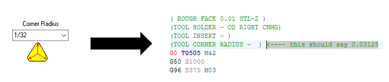
I am making some modifications to my lathe post processor and would like the post to output the tool nose radius in a comment so I do not need to manually type the radius. I am using a MPLFanuc post with some basic modifications to it. Is there a command I can call to get this information from Mastercam? I would like to have a similar comment for grooving tool width as well if this is possible. Any help here would be greatly appreciated. Thank you