RecceDG
-
Posts
55 -
Joined
-
Last visited
-
Days Won
3
Content Type
Profiles
Forums
Downloads
Store
eMastercam Wiki
Blogs
Gallery
Events
Everything posted by RecceDG
-
 Is there a way to get Mastercam to show the lateral force at the tool and how much power is being used, at any given point in the toolpath? Thanks!
 -
Well it turns out that getting Mastercam to violate the right-hand rule is trickier than I thought, so I flipped my Y axis direction on the machine and got on with it.
-
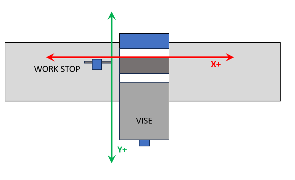
To what effect? That corrects the jog handle numbers, but assuming the part zero remains "back left", now X coordinates "in the part" are positive, but Y coordinates are negative. With the orientation as per diagram, all XY "in the part" are positive.
-
So I have finally gotten my mill conversion done to the point where I can actually start cutting metal! Huzzah! Up to this point, all my machine work has been on a lathe (which is its own deal) or on a gantry router. On the gantry router, X0 Y0 is left front of machine, and Z0 is set to either top of stock (my usual setup) or rarely, surface of table. I have a workstop installed that is a right-angled step on the table at a known XY. The work is pulled up tight against the stop then clamped down, so I only ever have to probe the stock top height. On the mill, that won't work, because the moving jaw of the vise is outboard where the inboard jaw is fixed. That suggests an axis orientation as per the attached diagram - and because I am master of my own domain as far as machine configuration goes, I can easily set that up. I presume I can tell Mastercam that part zero is upper left and Y increases coming out. Aside from this meaning two different axis orientations depending on if the part is router or mill - and that the numbers on the jog handle are backwards in Y - I can think of no downside to this. Thoughts?
-
Is it just me, or is Tool Manager kinda... lacking?
RecceDG replied to RecceDG's topic in Industrial Forum
Doesn't work. It applies blanket parameters by material with no tie back to the tool. It should be tool number AND material AND cut type, not tool number OR (material AND cut type). My tools have different flute counts, helix angle, rake angles - you can't just call them "carbide" or whatever. -
Is it just me, or is Tool Manager kinda... lacking?
RecceDG replied to RecceDG's topic in Industrial Forum
Well with Mastercam for Solidworks going away (!) I can see them wanting to improve the CAD side to make Mastercam more of a single-solution, where right now its more Solidworks for CAD and Mastercam for CAM. Which makes the tool management shortcomings more baffling. I get that Mastercam doesn't want to be tool inventory management, but you'd think there'd be an easy way to associate feeds & speeds, by material and cut type, to individual tools. -
I've just started XMas leave so I have 3 glorious weeks to play with tools, and the final parts for my CNC conversion of my bench mill came in, so I'm doing my homework and setting up Mastercam for use with the new machine. Part of that is setting up the tool library in Mastercam and Mach 4 and labeling assemblies. So I modeled my toolholders in Solidworks, exported them to STEP files, used Tool Manager to import them as holders. Then went through all my tools, created those. Then finally created assemblies using the definitions. T1 through T13, all GTG (I have a drill chuck, a shell mill, and an ER collet holder that I'll do later) So I have spent more than a couple of hours in Tool Manager learning how it works and setting up my tools. And... I'm a little underwhelmed by the granularity of the data it stores and the usefulness of the data relationships. Like, it has the ability to select "roughing", "finishing", or both, and set Ap and Ae as a percent of D... but not separate feeds and speeds for roughing and finishing. I can go into the stand-alone tool manager and define cut parameters and materials... but I can't tie them to either tools or assemblies? Changing the tool data doesn't update the related assembly? I should be able to, in tool manager, be able to say "when using this tool to rough slot 6061, Ap is 1D, Ae is 1D, SFM is 1000 and Fz is 0.003"/tooth. When rough shoulder cutting 6061, Ap is 3D, Ae is .5D, SFM is 1200 and Fz is 0.0035"/tooth" and so on - and then creating a new toolpath should pull these values from the tool DB. Specify cut data per tool, per material, per roughing/finishing, per slotting/shouldering/facing etc. Am I missing something? I feel like I have to start a notebook with a page per tool that records cut data, because Tool Manager can't do it. Am I wrong?
-
Arrrgh.... never mind. You just start typing the number and it enables text entry. I'll leave the thread up for the next dumbass to find.
-
With the CNC conversion of my bench mill nearing completion I'm doing my homework and creating my tool library of tools, holders, and assemblies. I've got most everything sussed out, save this: I see how to adjust tool stickout graphically by grabbing it in the interface and sliding along the linear scale, but I see no way to manually set that value. I can't just click on the numeric field and type it in. There's probably some n00b trick that I don't know about.... How do I do it? Thanks!
-
I feel like I'm missing something here, in that I'm not following the last couple of posts. So I'm going to do a part with a 2D pocket in it. Sketch stock X/Y extents in Solidworks, extrude up Z, sketch pocket on upper Z face, extrude cut down to depth. In this case I'm not doing a facing cut or anything, just the pocket, so stock extents are part extents. Go into the Mastercam tab, define stock extents as geometry extents, and I think I have to click on a corner to get the stock to line up with the geometry instead of being centered on it. I also have to pick a plane, so I use whatever plane gets me +Z as "up" (I think it is Mastercam Top, might be Mastercam Front) So now I have the gnomon on the left front (X/Y) corner where I want it, but Z0 is on the bottom of the part and I want it on the top. So Planes Manager, Add New Plane, From Geometry, pick the top face of the part, call it "Stock Top" and check WCS, T, and G. Now the gnomon is correctly located on the top face, left forward corner like I want. New Pocket operation. Select the bottom face in the pocket for geometry. MC generates a chain around the edge at the bottom of the pocket. Back to cut parameters. Fill in tool, speeds, feeds, roughing steps, yadda yadda. Preview cut and it's what I want. Post code. Examine code, and instead of Z values being negative (down from zero) they are positive (up from part base). Curse. Swear. Tear hair. Back to pocket parameters. Discover an option to pick WCS plane (why is this not inherited from planes manager?). Set WCS plane as "stock top". Regen code. Toolpath is identical. Post code, Z heights are negative, as expected. Nowhere did I mess with "depths", incremental or not. What did I miss?
-
OK, thanks. When I get home I'll see what I have set.
-
Can you post a screenshot so I can see what you mean?
-
Back to XCarve. I need to do a better job of setting up machine definitions so I can easily tell MC which machine I'm on - especially because I can go for months without using MC. I wound up using the default mill definition for this job which doesn't use my GRBL post processor, so I had to hand-edit a bunch of the gcode. This was a basic engrave job. Do the lettering in Adobe Illustrator, export as DXF, pull that into SW as a sketch, extruded cut, 2D flat mill out the pockets. Not a "vcarve" engrave job with a chamfer bit; a flat-bottom mill job. Mastercam refused to recognize the faces at the bottom of some of the letters as closed chains until I changed the chain tolerance from 0.0001" to 0.001". Not at all sure why. I prefer to have my work zero be the top of the stock, usually front left corner. One thing that Fusion does very well is it makes setting the WCS origin super easy as part of the stock definition. MC, I need a new plane, so go to Planes Manager, "Add New Plane", grab the geometry that is the top of the stock, name this plane "Stock Top", set it as WCS, G, and T. Display shows the gnomon in the right spot. ...but then the toolpaths are offset by 0.75" (the thickness of the stock), like the Z zero was the bottom of the stock. WTF? And that's when I find as option in the pocket operation to pick the zero plane... Set that to "stock top" and now everything works as expected. Why does this not reference the WCS plane in the plane manager? Why in the name of Lob does the pocket op have a separate plane select option? But I got my code exported and it cut fine, so huzzah!
-
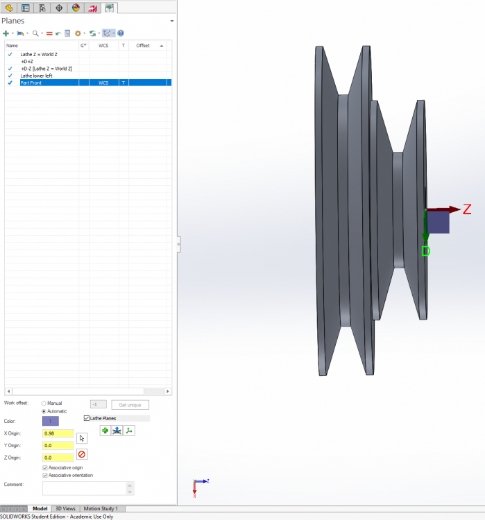
...and I just redid the tool, and the new version doesn't work - "unable to find intersections" - so I clearly missed a step somewhere. Here's my zero problem. Planes setup. Picked a plane on the part front. Set the offset. Gnomon is is correct position at the origin I want. But the toolpath uses the origin at the part base - the home position for the tool here is Z=0, which makes it easy to see. It's screwed up even before it gets into post - comes into MC in the wrong orientation (upside down). ...but that might be in the tool definition. I just redid it, and checked some different boxes to ensure left spindle/bottom turret, but now it doesn't like it at all.
-
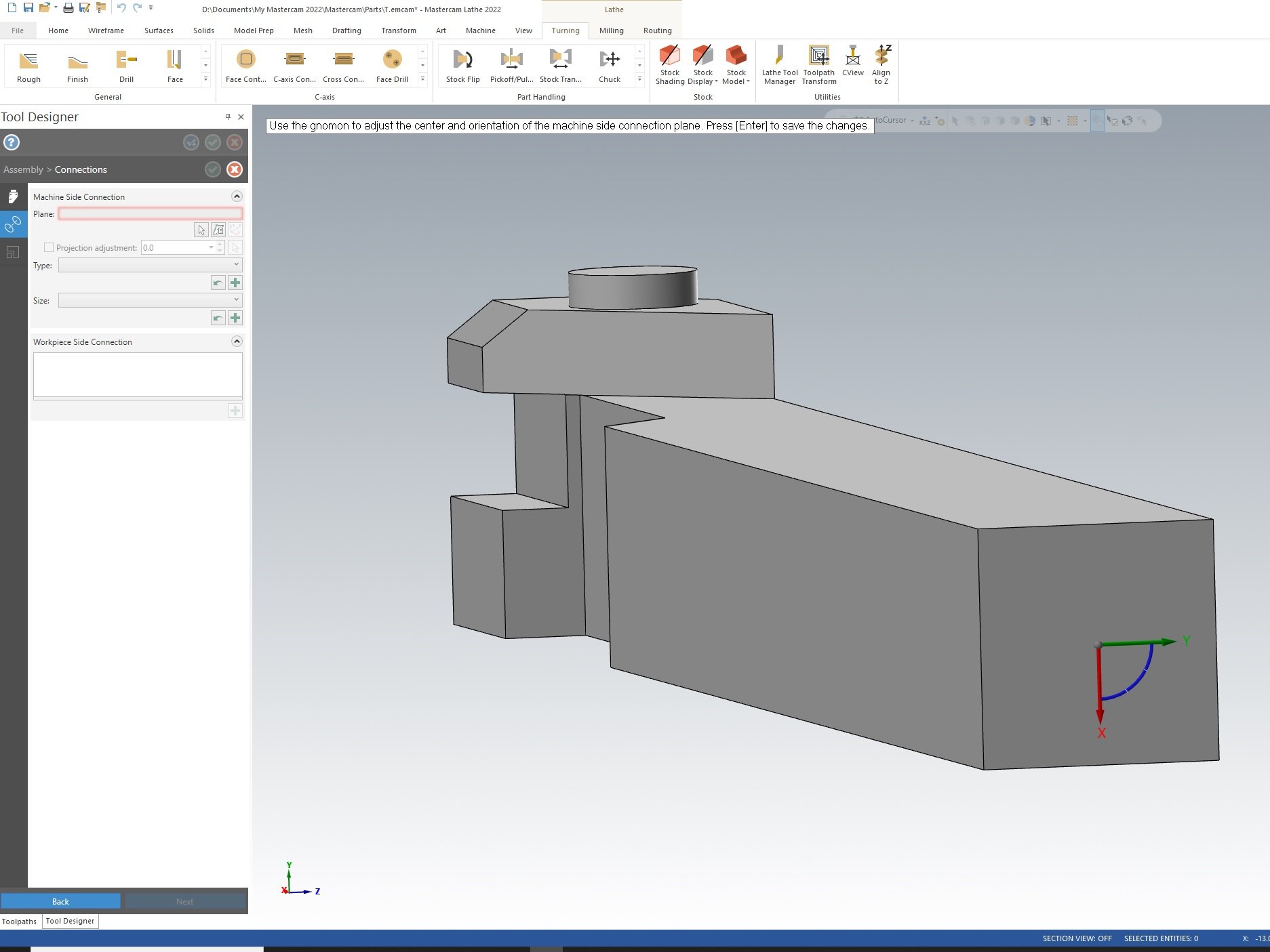
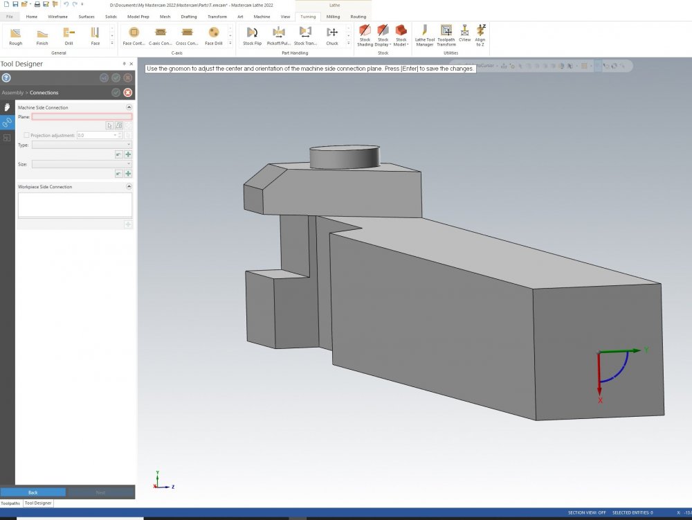
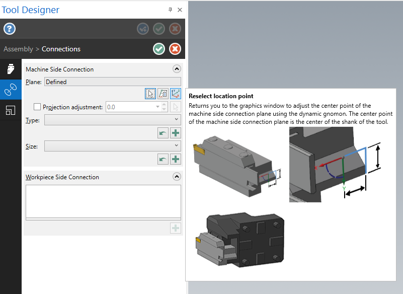
As I understand it, MC4SW is more-or-less standalone MC running in a SW instance, so all the UI elements, shortcut keys etc should be the same. But I have to use MC standalone to edit 3d tools, so that's moot. Anyway, here is an example. This is the holder for the tool in question. I rotated in in SW before exporting as STEP so that it would be oriented the same way in the machine - that is, the origin in the lower left is oriented the right way, with the long axis of the tool in X, Z+ going right, and Y+ going up. The lathe in question is a CNC converted bench lathe, not a slant lathe, so the spindle is left and the toolpost is on the near side. The screenshot shows the step where I define the machine connection. Now the tooltip shows the X left and the Y down, so I rotated it accordingly... but I do not understand why it wants THAT orientation - should it not match the lower-left axis orientation? Is there a way to change the dynamic gnomon (the one on the back of the tool) to control different axis?
-
Oi, back to the lathe today. I have a Kaiser Thinbit toolholder and insert thingy that I use for groove-turning. I decided to try modelling it in 3D, so I modeled it in SW, exported it as STEP, brought it into MC (standalone, as I figured out that you cannot build 3D tooling in MC4SW) and after a TON of trouble getting the insert oriented right, successfully brought it in to MC4SW and created a groove toolpath that worked. Although for some damned reason it came in upside-down and ran the spindle backwards, defeating the purpose of modelling the holder because now it was facing the wrong way. At least - because the insert is symmetrical - the toolpath still worked. When editing the tool, I wound up using that gnomon tool a lot - is there a way to get it to switch axis? Like if I'm on XY, can I hit a key to get it XZ, then YZ? Then, it turned out I modelled the part with the origin chuck-side (the back of the part) instead of tailstock-side (the front of the part. So Where I'm used to cutting Z negative, this was all Z positive. OK, no problem, I'll just move the WCS and T plane - and while I could get the gnomon to point in the right direction and be in the right place, NOTHING would make those toolpaths recognize the new origin point. NOTHING. I wasted SO MUCH TIME trying this. Eventually, I gave up, touched off the front of the part, jogged Z back to the back of the part, and set Z zero on the machine (which worked) but Dear Sweet Lob the Lobster God why would this not work?
-
#region Tool change / stage tool ptlchg$ #Tool change pcuttype toolchng = one if mi1$ = one, #Work coordinate system [ pfbld, n$, *sg28ref, "X0.", "Y0.", e$ pfbld, n$, sg92, *xh$, *yh$, *zh$, e$ ] inhibit_probe$ if prog_stop = 1, pbld, n$, *sm01, e$ if prog_stop = 2, pbld, n$, *sm00, e$ pcom_moveb pcheckaxis c_mmlt$ #Multiple tool subprogram call ptoolcomment comment$ pcan result = newfs(15, feed) #Reset the output format for 'feed' # Changed by DG 02/01/2022 # Same deal - need to trap and inhibit tool change # We will issue a hard stop here as this subroutine is called for toolchanges # Other than the first # pbld, n$, *t$, sm06, e$ sopen_prn, "REMOVED A TOOL CHANGE - STOPPING ", *t$, sm06, sclose_prn, e$ pbld, n$, sm00, e$ pindex sav_absinc = absinc$ if mi1$ > one, absinc$ = zero if use_rot_lock & (cuttype <> zero | (index = zero & prv_cabs <> fmtrnd(cabs))), prot_unlock if convert_rpd$, pconvert_rpd # Changed by DG 02/01/2022 # Same deal with spindle speed and mixing other codes with G0 #pcan1, pbld, n$, [if gcode$, *sgfeed], *sgcode, *sgabsinc, *sgplane, pwcs, pfxout, pfyout, pfcout, # [if nextdc$ <> 7, *speed, *spindle], pgear, [if gcode$, *feed], strcantext, e$ pbld, n$, [if nextdc$ <> 7, *speed, *spindle], pgear, e$ pbld, $n, *sgabsinc, *sgplane, pwcs, e$ pcan1, pbld, n$, [if gcode$, *sgfeed], *sgcode, pfxout, pfyout, [if gcode$, *feed], strcantext, e$ if use_rot_lock & cuttype = zero, prot_lock pbld, n$, sg43, *tlngno$, pfzout, pscool, pstagetool, e$ absinc$ = sav_absinc pbld, n$, sgabsinc, e$ pcom_movea toolchng = zero c_msng$ #Single tool subprogram call !xnci$, !ynci$, !znci$ Done. Thanks!
-
I've made a bunch of progress. These changes: #region Start of file psof0$ #Start of file for tool zero psof$ psof$ #Start of file for non-zero tool number probe_head$ pcuttype toolchng = one if ntools$ = one, [ #skip single tool outputs, stagetool must be on stagetool = m_one !next_tool$ ] pbld, n$, *smetric, e$ if convert_rpd$, pconvert_rpd # Changed by DG 01/01/2022 to get rid of spurious G0 and G80 # pbld, n$, [if gcode$, *sgfeed], *sgcode, *sgplane, scc0, sg49, sg80, *sgabsinc, [if gcode$, *feed], e$ pbld, n$, [if gcode$, *sgfeed], *sgplane, scc0, sg49, *sgabsinc, [if gcode$, *feed], pwcs, e$ inhibit_probe$ sav_absinc = absinc$ if mi1$ <= one, #Work coordinate system [ absinc$ = one pfbld, n$, sgabsinc, *sg28ref, "Z0.", e$ pfbld, n$, *sg28ref, "X0.", "Y0.", e$ pfbld, n$, sg92, *xh$, *yh$, *zh$, e$ absinc$ = sav_absinc ] pcom_moveb pcheckaxis uninhibit_probe$ c_mmlt$ #Multiple tool subprogram call ptoolcomment comment$ pcan # Changed by DG 01/01/2022 to inhibit tool call because GRBL doesnt like it # Might be an idea here to output an optional stop in case we have multiple tools in a file # Instead of one tool per file as is my personal practice # Even better if somehow a comment can pop up in UGS or other sender programs # Although the best way would be for GRBL to support M6 # Or for UGS to catch it and do something reasonable # For now, we just ignore the tool change, which has potential for disaster # pbld, n$, *t$, sm06, e$ sopen_prn, "REMOVED A TOOL CHANGE ", *t$, sm06, sclose_prn, e$ # Move spindle and speede to here DG pbld, n$, [if nextdc$ <> 7, *speed, *spindle], e$ pindex if mi1$ > one, absinc$ = zero if use_rot_lock & (cuttype <> zero | (index = zero & prv_cabs <> fmtrnd(cabs))), prot_unlock if convert_rpd$, pconvert_rpd # Changed by DG 01/01/2022 to move spindle speed and coordiantes earlier and eliminate some spurious stuff GRBL doesnt like # pcan1, pbld, n$, [if gcode$, *sgfeed], *sgcode, *sgabsinc, pwcs, pfxout, pfyout, pfcout, # [if nextdc$ <> 7, *speed, *spindle], pgear, [if gcode$, *feed], strcantext, e$ pcan1, pbld, n$, [if gcode$, *sgfeed], *sgcode, pfxout, pfyout, pgear, [if gcode$, *feed], strcantext, e$ if use_rot_lock & cuttype = zero, prot_lock result = force(feed) # Force output of feed next time it's called for output # Changed by DG 01/01/2022 to eliminate the tool length call # pbld, n$, sg43, *tlngno$, pfzout, pscool, pstagetool, e$ pbld, n$, pfzout, e$ absinc$ = sav_absinc pbld, n$, sgabsinc, e$ pcom_movea toolchng = zero c_msng$ #Single tool subprogram call #endregion Now produces this: % (O0000TEST) (DATE=DD-MM-YY - 01-01-22 TIME=HH:MM - 17:59) (MCAM FILE - M:\DOCUMENTS\DENNIS\SOLIDWORKS PROJECTS\MILL CONTROL PANEL\MILL CONTROL PANEL.SLDPRT) (NC FILE - D:\DOCUMENTS\MY MASTERCAM 2022\MASTERCAM FOR SOLIDWORKS\MILL\NC\TEST.nc) (MATERIAL - ALUMINUM MM - 2024) ( T2 | 1/4 SPOTDRILL | H2 ) G20 G17 G40 G49 G90 G54 ( REMOVED A TOOL CHANGE T2 M6 ) S27153 M3 G0 X1.3118 Y1.9291 Z.5 G1 Z-.075 F27.17 G0 Z.5 Now I just need to examine the end-of-file stuff and see what makes sense. I'm using as light a hand as I can on the generic FANUC post processor and preserving a ton of extraneous features - I can't help but wonder if it would be worthwhile to do a stripped-down GRBL post that doesn't provide the opportunity to accidentally turn on stuff GRBL does not support.
-
OK, I have successfully run some XCarve operations and have an idea now what GRBL doesn't like. Here is a quick extract of a simple spot drill op: % O0000(MILL CONTROL PANEL OP 1 V2 - SPOT DRILL) (DATE=DD-MM-YY - 31-12-21 TIME=HH:MM - 13:51) (MCAM FILE - M:\DOCUMENTS\DENNIS\SOLIDWORKS PROJECTS\MILL CONTROL PANEL\MILL CONTROL PANEL.SLDPRT) (NC FILE - D:\DOCUMENTS\MY MASTERCAM 2022\MASTERCAM FOR SOLIDWORKS\MILL\NC\MILL CONTROL PANEL OP 1 V2 - SPOT DRILL.nc) (MATERIAL - ALUMINUM MM - 2024) ( T2 | 1/4 SPOTDRILL | H2 ) G20 G0 G17 G40 G49 G80 G90 T2 M6 G0 G90 G54 X1.3118 Y1.9291 A0. S27153 M3 G43 H2 Z.5 G1 Z-.075 F27.17 G0 Z.5 X2.6118 G1 Z-.075 F27.17 G0 Z.5 M5 G91 G28 Z0. G28 X0. Y0. A0. M30 % Now here's a list of things GRBL did not like: 1. O0000 on first line 2. G0 G17 G40 G49 G80 G90 - Didn't like G0 with no following, axis, doesn't understand G80 3. Doesn't support tool changes, so need to eliminate T2 M6 (could be an optional stop with an optional move to a manual tool change position) 4. G0 G90 G54 X1.3118 Y1.9291 A0. S27153 M3 - spurious G90 and G54. Spurious A0. S and M3 should be on separate line 5. G43 H2 Z.5 - Doesn't support G43 6. G91 G28 Z0. - I think this works (I deleted it for test run) should fully retract spindle 7. G28 X0. Y0. A0. - Spurious A0. Not entirely sure if this is the right place to end. Need to know where in post this is controlled Should look like: % (MILL CONTROL PANEL OP 1 V2 - SPOT DRILL) (DATE=DD-MM-YY - 31-12-21 TIME=HH:MM - 13:51) (MCAM FILE - M:\DOCUMENTS\DENNIS\SOLIDWORKS PROJECTS\MILL CONTROL PANEL\MILL CONTROL PANEL.SLDPRT) (NC FILE - D:\DOCUMENTS\MY MASTERCAM 2022\MASTERCAM FOR SOLIDWORKS\MILL\NC\MILL CONTROL PANEL OP 1 V2 - SPOT DRILL.nc) (MATERIAL - ALUMINUM MM - 2024) ( T2 | 1/4 SPOTDRILL | H2 ) G20 G17 G40 G49 G90 G54 S27153 M3 G0 X1.3118 Y1.9291 Z.5 G1 Z-.075 F27.17 G0 Z.5 X2.6118 G1 Z-.075 F27.17 G0 Z.5 M5 G91 G28 Z0. G28 X0. Y0. M30 % I'll dive into the post later and see what I can figure out, but I'd be happy to accept pointers if anyone was so inclined.
-
Back on topic: I've got an XCarve job coming up (cutting the switch and gauge holes in a piece of aluminum plate that will be the faceplate for my mill control panel) so I will be doing the machine definition for the XCarve and the postprocessor for GRBL over the XMas break. Yay!
-
So this: https://www.tribology-abc.com/calculators/e3_6f.htm Plus this: https://www.makeitfrom.com/material-properties/UNS-C93200-SAE-660-Bearing-Bronze Suggests 8750 lbs load before the threads strip. The Inch PV calculator thus states that I can go 760 RPM at full load in bronze. So I should be good.
-
So I found this: Inch PV Value Calculator | Nook Industries And this: Lead Screw Torque and Force Calculator (daycounter.com) Working backwards, I know my stepper is rated for 2Nm holding torque and it is geared down 1:2. Assuming the nut is brass and CoF is 1.2, that means I can deliver 1200lbs before stalling the motor. So the next question is, how much force can the M10x1.0 brass nut absorb?
-
They are both hybrid steppers with encoders on them; the drivers won't let them miss steps. If they do, the driver faults out, sets an alarm line, and the machine estops.
-
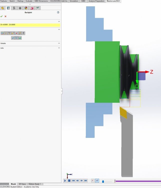
Given the construction of the Z axis, I think I'm OK cranking up the Z rapids - and honestly, with the duty cycle of this machine, there's just not a ton of time spent moving; it's not like the machine is running 24/7. But at the same time, speeding up my cycle times is nice. The X rapids I'm way more hesitant about. Here, I'm not so much looking at cycle times, but making sure the axis is fast enough to keep up with 2-axis moves for chamfers or radii. At the slow speeds I had the axis set for, at faster spindle RPMs I was getting into max in/rev that I'd actually want to use (like 0.008"). Bumping the max speed up to 35 in/sec means I can do about 0.015"-ish in/rev at 3000 RPM which is more headroom. As far as the nut goes, yeah, some SAE 660 bronze is probably a better alloy. It's a part I can make too, it's a cylindrical pin that fits into a hole in the carriage, cross-drilled and threaded. If I get a form tap I should be able to make a nice smooth thread. *sigh* I thought I was done making lathe parts. I really wish I could find some sort of formula or table that detailed max thread rotational speed by thread pitch, diameter, and material. I also wish I knew how to calculate the force needed to drive a cutting tool into a part. What I have now is the most powerful stepper I could fit, geared down 1:2, and then the M10x1.0 leadscrew thread. The idea was to maximize the force the crosslide could generate so that the stepper would never stall - at the cost of rapid speed. For a while, the limiting factor was the power of the spindle motor (so sometimes when parting I could stall the spindle) but that was largely an artifact of the fabricobbled spindle motor pulley, driving a metric belt with an SAE pulley. Once I cut my own motor pulley I appear to have eliminated belt-slip stalling, and now I suspect the torque limit is the 9mm GT2 X axis drive belt. I wish I knew how to work out these forces from first principles, even as a rough approximation to see if I'm in the ballpark. The lathe performs great, but parting off (although it has gotten much better) is always a bit of an adventure. The sad truth though is that the underlying bar-bed design is just too flexy, and at some point, I'm just turd-polishing. I will eventually pick up one of these: https://www.kingcanada.com/en/products/metalworking/metal-lathes/kc-1236ml-12-x-36-gearhead-metal-lathe and convert it. Luckily, all my CNC-bits will port over. Here's what 175 in/min Z and 35 in/min X looks like:
-
Not this one. It's a brass cylinder crossdrilled - not axially drilled - with the leadscrew thread.