


ThickChips
-
Posts
84 -
Joined
-
Last visited
ThickChips's Achievements
")


-
@Kyle F I'll have to play with it. I tried reflow and edit uv but couldn't quite figure it out.
-
I think I found a solution. A simple 3D contour. The challenge for me was creating 3D wireframe from the solid. (I tried getting flow-line like wireframe from a surface but none of them followed the contour? U/V is left-right / up-down.) First, i created a surface from solid. Then simply used "offset chain" (which is oddly placed to the far right in my toolbar, didn't know that existed in mcam). 3D (2D in menu) contour, select chain, disable compensation (ball mill), then offset x number of passes * distance. Thanks for the help. Going to load into machining center soon. Fingers crossed.
-
@Kyle F Ah darnit. I'm actually in 2022...
-
I selected the top surface as the "model geometry" and then 2 containment boundary's (model edge on each side of island). Can the geometry be wire frame?
-
@Kyle F Thanks for your help. I'm trying a surface blend, but keep getting error "warning - at least two chains are required."/
-
@JParis OK thank you
-
@JParis Thanks for your help with this. Unfortunately, we're still on 2023. I assume no way to open without upgrading? Thanks
-
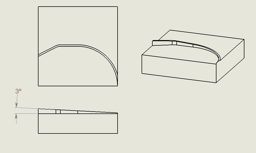
Hello all, I have an 'island' which follows an irregular profile. It's top surface is on a 3 degree draft. Customer needs this feature re-surfaced. 3D is not my wheel house. Usually spiral flowline accomplishes the simpler stuff for me. We do not have a 3D package, unfortunately, but they "work" sometimes for simple things. (i'm not sure how exactly). My plan was to do a 3D ramp along the profile with a flat endmill, or a corner rad endmill, following the profile of the contour. Would anyone mind taking a look for me and offering their .02 on a toolpath/solution? edit: Some more information . 3 axis Haas. There are some features beside the island that may need to be avoided on the actual part. There is about .05" per side of clearance. Thanks a lot 3D_FACE_EXAMPLE..mcam
-
Macro program - GT operator illogical behavior
ThickChips replied to ThickChips's topic in Industrial Forum
Argggg, were beating a dead horse here. You must understand, I attempt to defend my position respectfully. Its not personal. @JParis and you have both helped me many times with CAM related issues. So, please know that I mean no disrespect to the forum as a whole or any members: I posted to understand why GT is not behaving properly under my circumstances. And again, respectfully, the context of my program has absolutely nothing to do with the problem I have extensively laid out here, nor am I interested in sharing it. Do you recognize that a logical operator performing UNPREDICTABLY is a MASSIVE problem for computing? Could I patch this problem with a different operator and move on? Probably. So, then I ignore the aforementioned fact that an operator is behaving illogically and HOPE that it doesn't happen again? I am not interested in making my program work. I am interested in ensuring every program I write works when I use the GT operator. All of that ^^^ is based on the assumption that we both AGREE that GT is not performing properly according to the spec of the language. It is unclear whether you accept that premise. So, why do I accept that premise (that testing two equal numbers for GT returns false)? Why do I accept that premise? Well, mostly--- because almost all computer programming language have this behavior. I know this for a fact, and I also tested my sanity in those other languages. GT operators perform FALSE when comparing two equal values. Its just... logical. Perhaps I am wrong, which is a real possibility. That GT in the RS-274 standard performs unlike other programming languages, but I doubt this. (Further, my tests suggest this is NOT the case- it is a rounding or numerical error or a look-ahead error) Lastly, if we can AGREE that GT is not operating logically in the FAILED tests, then we can talk about things like Look-Ahead or Rounding, which in my belief is heading more in the right direction. I'll conclude: I have Haas working on this so I will report back with what the issue is. I appreciate the discussion. -
Macro program - GT operator illogical behavior
ThickChips replied to ThickChips's topic in Industrial Forum
Precisely - it CANT BE - so why is GOTO 1000 being executed? And again - CORRECT. Therefore, WHY is GT returning TRUE (going to 1000)? -
Macro program - GT operator illogical behavior
ThickChips replied to ThickChips's topic in Industrial Forum
I've taken nothing personal. I'm merely pointing out what is true and what is not true. Someone may not like the way code is written, it doesn't change the fact that it is logically valid under the rules of the language. Respectfully, there is a lot of fallacies within your comment.... No infinite loop is possible under these tests. IF GT is true, then it goes to 1000. If GT is false, it continues execution. I would like to see a code example that demonstrates an infinite loop. Next, you say this, This is false! I provided the tests, did you review them? Test 1 checks: IS .25 > .25? Result is NO - PASS Test 2 checks: IS .9 > .9? Result is YES - FAIL <-------------- NOT TRUE -
Macro program - GT operator illogical behavior
ThickChips replied to ThickChips's topic in Industrial Forum
@JParis Sorry, perhaps you could explain what part of the statement is illogical... If you think that ".900000 > .900000 = TRUE" is logical, then you're being... illogical. GT operators were included in the language for a reason. -
Macro program - GT operator illogical behavior
ThickChips replied to ThickChips's topic in Industrial Forum
Yes and even if I didn't this isn't exactly relevant because the behavior is illogical. EQ is a VALID condition under the context, and so is LT. Meaning that EQ doesn't have to be accounted for. GT needs to be accounted for. EDIT: I misinterpreted LE/GE comment. My reply of 'Yes' should be 'No' -
Macro program - GT operator illogical behavior
ThickChips replied to ThickChips's topic in Industrial Forum
Update: Added a 7th test with a PASS (Inserted M00 with "working inputs" from Test #1) (TEST 7 - PASSES) % O0000 (MACRO) #512 = 5.0 #513 = .05 #601 = [[#512*#513]] (=.250) #510 = 1.00 #511 = .500 M00 (<----- M00 inserted) #602=[#510-#511]/2 (=.250) IF[#601GT#602]GOTO1000 (pass - does NOT goto 1000) #3000=1(PASS) N1000 #3000=1(FAIL) M30 % -
Macro program - GT operator illogical behavior
ThickChips replied to ThickChips's topic in Industrial Forum
@Zoffen Man, I was really hoping this was the golden ticket (G103 p1). Sadly, it didn't seem to affect behavior. Tried at top of program. Before the line. Adding empty blocks before the block in question. No effect. @JParis @crazy^millman The process isn't odd. The complete context just isn't provided. Nevertheless, to rule out any doubt I used a variant of @JParis example to isolate the issue. And my findings are quite... unpredictable. I did some extensive testing this morning. Below describes a number of tests and their results. Here are the cliff-notes: It is important to understand all tests have been run under inputs that yield identical results for #601 and #602. That is to say #601=#602 in all tests, regardless of inputs. No testing was done where they are not equivalent, and I assume said tests would pass fine. G103 P1 had no affect - but I didn't include it in the tests below - more testing would be ideal. M00 before the IF statement directly affects this behavior. (I know the M00/M01 affects look ahead according to haas docs) The inputs directly affect the behavior - So, we assume some sort of numerical error is at play. (namely when #601 and #602 = .900000) it causes issues. Here are the tests - also attached as individual programs. Tests.zip (TEST 1 - PASS) % O0000 (MACRO) #512 = 5.0 (pass with decimal or integer) #513 = .05 #601 = [[#512*#513]] (=.250) #510 = 1.00 #511 = .500 #602=[#510-#511]/2 (=.250) IF[#601GT#602]GOTO1000 (pass - does NOT GOTO 1000) #3000=1(PASS) N1000 #3000=1(FAIL) M30 % (------------------------------------------------) (TEST 2 - FAIL) % O0000 (MACRO) #512 = 9. #513 = 0.1 #601 = [[#512*#513]] (=.9 <------- inputs have changed) #510 = 2.3 #511 = .500 #602=[#510-#511]/2 (=.9) IF[#601GT#602]GOTO1000(FAIL! GOES TO 1000) #3000=1(PASS) N1000 #3000=1(FAIL) M30 % (------------------------------------------------) (TEST 3 - PASS) % O0000 (MACRO) #512 = 9. #513 = 0.1 #601 = [[#512*#513]] (=.9) #510 = 2.3 #511 = .500 #602=[#510-#511]/2 (=.9) IF[ROUND[#601] GT ROUND[#602]] GOTO1000 (pass - does NOT GOTO 1000) #3000=1(PASS) N1000 #3000=1(FAIL) M30 % (-----------------------------------------------------) (TEST 4 - FAILS) % O0000 (MACRO) #512 = 9. #513 = 0.1 #601 = [[#512*#513]] (=.9) #510 = 2.3 #511 = .500 #602=[#510-#511]/2 (=.9) M00 (<------ NOTICE) IF[ROUND[#601] GT ROUND[#602]] GOTO1000 (FAIL! GOES TO 1000) #3000=1(PASS) N1000 #3000=1(FAIL) M30 % (-----------------------------------------------------) (TEST 5 - PASSES) % O0000 (MACRO) #512 = 13. #513 = .0625 #601 = [[#512*#513]] (=.8125 <------ INPUTS HAVE CHANGED!) #510 = 2.125 #511 = .500 #602=[#510-#511]/2 (=.8125) IF[ROUND[#601] GT ROUND[#602]] GOTO1000 (PASS - does NOT goto 1000) #3000=1(PASS) N1000 #3000=1(FAIL) M30 % (-----------------------------------------------------) (TEST 6 - PASSES) % O0000 (MACRO) #512 = 13. #513 = .0625 #601 = [[#512*#513]] (=.8125 <------ INPUTS HAVE CHANGED!) #510 = 2.125 #511 = .500 #602=[#510-#511]/2 (=.8125) M00 (<---- PASSES EVEN WITH M00) IF[ROUND[#601] GT ROUND[#602]] GOTO1000 #3000=1(PASS) N1000 #3000=1(FAIL) M30 %