Accurpress
-
Posts
5 -
Joined
-
Last visited
Accurpress's Achievements
")


-
I'm being nit-picky but I have 3 chains selected for model chamfer and I can't figure out a way to dictate the order in which the chains are machined. It's not doing it in an efficient manner so I tried moving the loops in the chain manager to the sequence that makes more sense. The chain manager shows one solid chain entity that trees out to 3 loops when expanded. It lets me move the order of the loops and saves it but doesn't change the actual order when i backplot it. I tried creating a new model chamfer tool path where I make sure to select the chains in the order I want and it still picks the the order that mastercam sees fit. Finally I created a model chamfer toolpath and only selected one entity. I then right clicked in chain manager and selected Add. I selected the two remaining entities and added them to chain manager so that now instead of 1 solid chain with 3 loops under it I now have 1 solid chain with one loop under it and another solid chain with 2 loops under it. The probelm I run into here is that when I back plot it i only get a toolpath for the first solid entity and it doesn't generate a toolpath for the second solid entity(which has 2 loops within it). I'm using Mastercam 2022. Am I overlooking where I can change the order or is changing the order not a capability with Model Chamfer?
-
I got it but now I think my main issue the first time was that the transform toolpath operation was glitching out. When I first started playing around I kept going back into the toolpath parameters multiple times and changing various things to see what it would do. I deleted the transform toolpath completely and created a new one and I'm 99% sure I ended up using the same setting that I tried before but this time it worked. I essentially unplugged it and plugged it back in again and it worked Thanks for the response because your example of showing it worked for you is was kept me at it instead of giving up
-
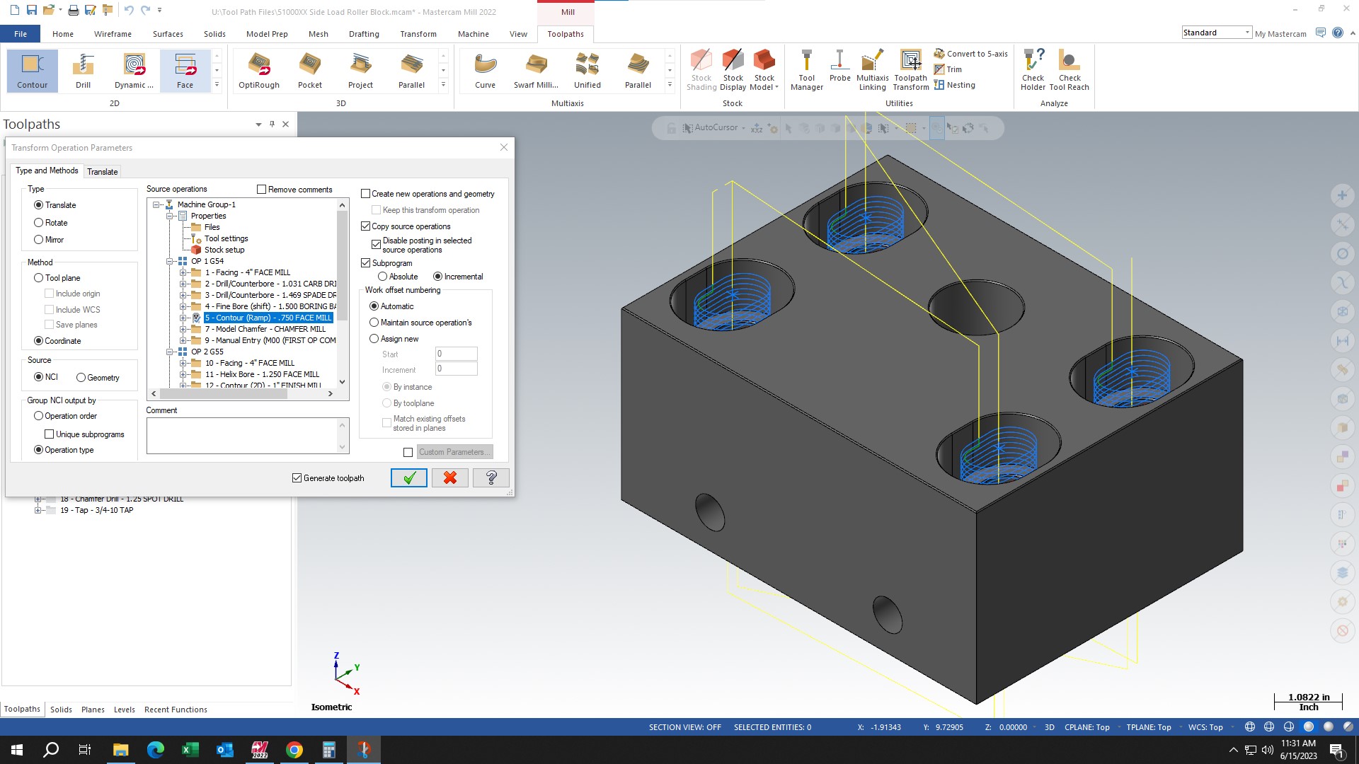
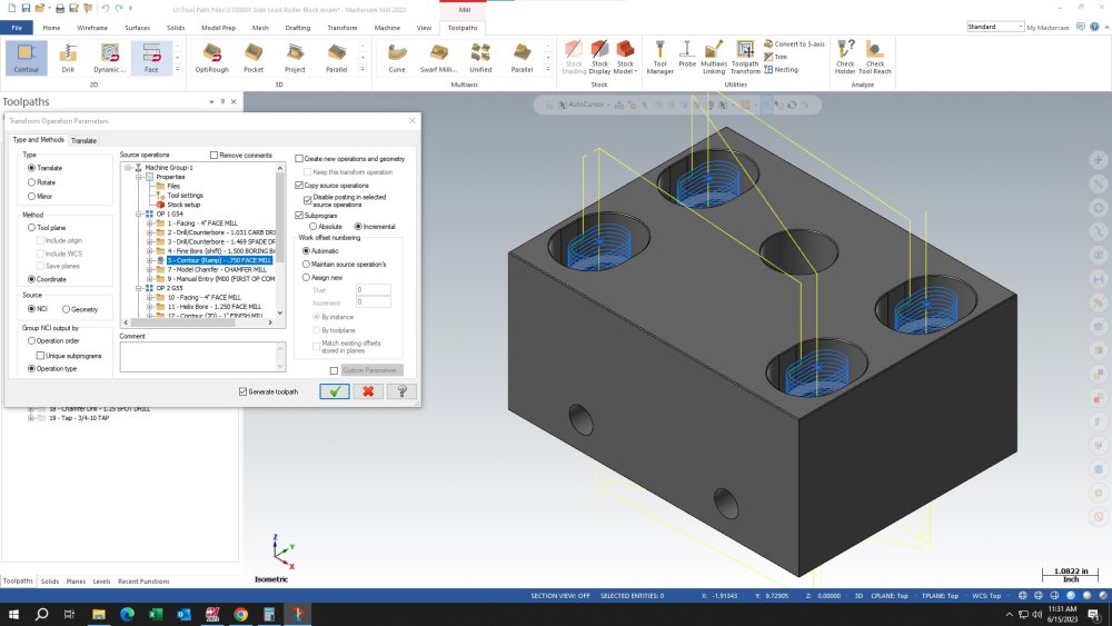
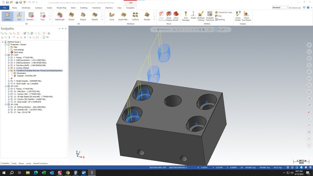
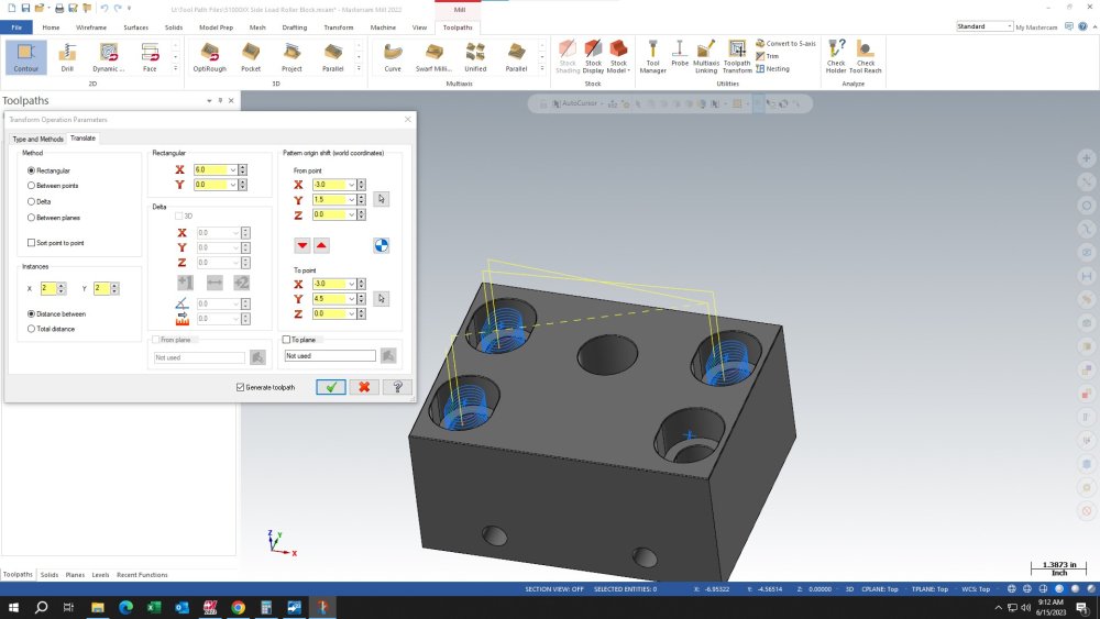
I generated a program using Mastercam but the machine I want to run it on doesn't have enough space for the file. Removed n#'s, spaces, and played with the arc tolerances a bit but it's still too big. Since we don't have ability to drip feed at the moment I guess the next thing is to use subroutines. I found this video which appears to do exactly want I want to do but the person making the video skips over the part where he used transform toolpath to select ALL the same geometries within the same part. I've found several videos of how to use toolpath transform to machine multiple parts( ie 4 vices running the same part in linear line) and I've found a couple videos of how to use transform toolpath(mirror mode) to copy geometry along an axis line but they're always using an example where they have one geometry and creating a second to have two total. I have 4 geometries that are mirrored in x and y but not by the same amount in both axis. I'm hoping I can select one geometry and then dictate where the other 3 will be placed but I've only been able to create 3 geometries in the correct place. I tried selection method of point to point but can only select a single "to point" rather than clicking all 3 additional points. Selection method rectangle got me close but I can't manipulate the numbers to get all 4. I'm guessing I can create geometry for 2 slots then use mirror for the other 2 slot but this would be a larger sub program than if I could create a sub routine for one slot. Is what I'm wanting to do even possible? To select one toolpath geometry then be able to select multiple areas within the part that aren't neatly arranged along a linear line? If someone could point me to a video or pdf I'd be grateful. I attached a couple pics if that helps
-
Brand new to Mastercam and stuck on something
Accurpress replied to Accurpress's topic in Industrial Forum
Bam! That was it. I didn't have wireframe visible when I was doing the window selection so it didn't grab those entities. I thought toggling what was visible on the Planes manager was merely to clear up a cluttered screen. I didn't realize that also dictates what can get changed or not changed..... now I know. Thank you so much for your response. Now on to the next very simple hurdle I can't overcome, haha -
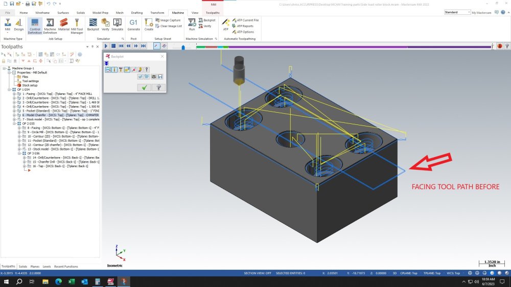
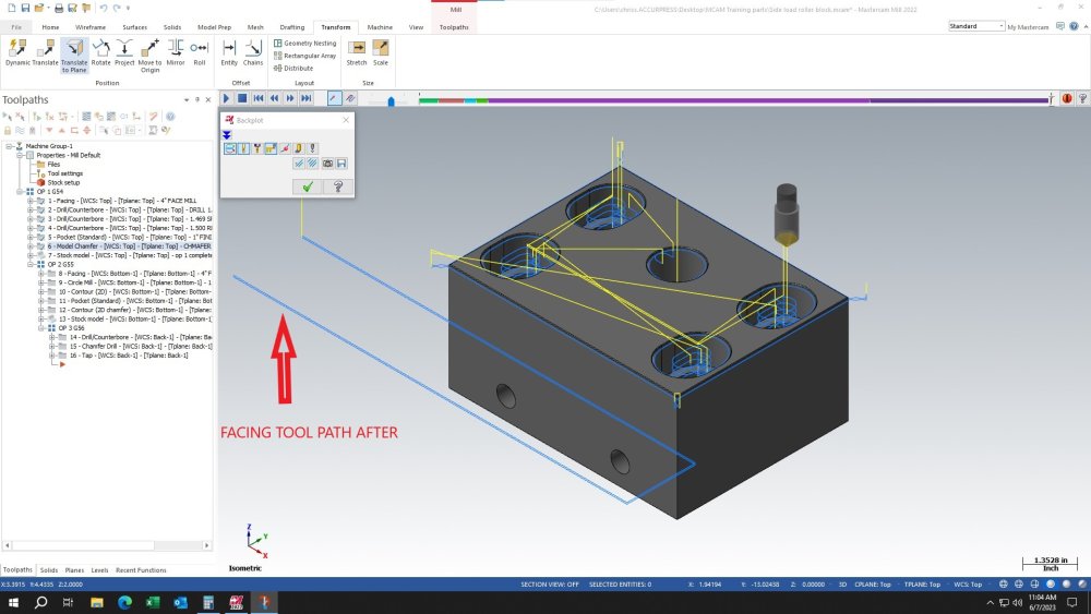
First time posting and if this isn't the right place my apologies. I'm attempting to teach myself Mastercam and I'm only a few days into it. I made a 3D model from a 2D print and then made a corresponding NC file. It was a struggle since trial-and-error was my main plan of attack, LOL. I originally did the operations for the part to be mounted in a vise on a vertical mill. After I was done I decided that I want to make the part in a horizontal mill instead. I'm wanting to match the y-axis print zero to the fixed jaw so for the vertical that puts the machining on the negative side of y. But now that the part is going in a horizontal mill that puts the machining on the positive side of y.... if I want to constrain the fixed jaw to the print zero. So I thought to myself, "this is why CAM exists, to quickly change processes that would take a long time to long hand a program" So I did dynamic transform to move the origin to the appropriate place so that I'm teaching the part at the fixed jaw. The trouble I'm having is that all my operations move correctly after regenerating with the exception of the face mill. The face mill operation is exactly 6 inches off, which happens to be the height of the part in y. I've tried scrapping the facing op and creating a new facing operation and I get the same result. I've gone through the operation parameters a bunch of times trying to figure out which value is off and I can't find anything but I'm a noob so..... I tried going into the Planes section of the parameters and doing a shift in the values there to attempt a "work shift" for just that operation but that didn't do anything. I'm to a point where the only way I know to fix it is delete everything and start from scratch which obviously wouldn't be ideal. Any ideas on where I'm screwing up? I attached a couple pics hoping that helps. Thanks