


Aaron Eberhard
-
Posts
1,404 -
Joined
-
Last visited
-
Days Won
103
Content Type
Profiles
Forums
Downloads
Store
eMastercam Wiki
Blogs
Gallery
Events
Posts posted by Aaron Eberhard
-
-
Took a quick look and it seemed easier to make a video than to write it all out (plus, I'm pretty much out of space to upload pictures and files!), hope that's okay:
-
 2
2
-
 1
1
-
-
1 hour ago, heavychevy2155 said:
We are using Cappsnc here at Blue Origin.
I haven't heard of 'em..
Their aircraft wing/surface panel tech looks really cool!
-
1 minute ago, Chally72 said:
The documentation is actually available on Mastercam.com, under the Learning- Documentation area:
Downloads – myMastercamThe "Multiaxis Help" files are the ones you're looking for. Of course, be aware that not everything in those files is implemented or interfaced as shown.
Right, but that would be the 2022_12 release since Mastercam 2024 is the latest version on there
.gif ":)") This new feature isn't in my copy of that doc..
This new feature isn't in my copy of that doc..
-
7 minutes ago, gcode said:
Thank you !!!
"latest release of MW documentation" is this something that is available the masses??
If you have google
The official channel is behind a login/password, but you can often find the quarter or two previous releases posted on various CAM forums.
They always do their documentation with 202x_yy, where it's the year and the quarter release. Since Mastercam always has the last of the previous year (note: This is an assumption that this is still the case), you can search for ModuleWorks End User Documentation 2023_12 to find the build that this year's Mastercam will use. I found this in a 2023_06 on a gibbs forum.
edit: I will say that I couldn't find the 2023_12 with <10 minutes of googlin'. That'll be available on the Mastercam portal when 2025 is officially released. If you stumble across a link, I'd be interested
-
I had to search for the latest release of MW documentation:
------------------
Automatic - Contact lines are placed in a way primarily minimizing the undercut to the target geometry and secondarily minimizing the allowance to the target geometry.
In case the target geometry forms a ruled surface, this strategy will try to create a toolpath with neither undercut nor allowance. In case the target geometry is no ruled surface, it will try to create the toolpath with the least undercut and allowance possible. This strategy is intended as the default, first-shot strategy. It contains a number of heuristics to create a reasonable tool axis tilting on a wide range of input geometries. Optionally, users can define tilt lines to fine tune the tool axis alignment in specific areas
-----------------
Automatic(legacy) - tries to place the tool on the swarf surface in a way that minimizes the area between the contact line from the lower to the upper curve and the swarf surface. Since the swarf surface is sometimes a parametric freeform surface (with double curvature), the area is not necessarily zero.
-----------------
Sounds like they improved a some of the cases where automatic choked up, but are acknowledging that it might break some other situations they couldn't test for?
-
1
-
-
For 90% of people, the CIMCO add on will be way less setup pain and get you there faster, cheaper, and easier utilizing the I+ macros already set up on the machine. For 10% of the people, I haven't seen anything else on the market give the ease of use of setting up complex logic (multiple nested If/Then/Else logic) like P+ can do.
Inspection+ are the macros that ship with the probe on your machine. If you use the GoProbe app on your phone (or the Renishaw manual) to enter, say, G65P9901M2.D0.5S54. to probe a .5" bore, that's Inspection+.
Productivity+ was developed by Renishaw as a stand alone program (yes, you can buy just P+, not integrated into Mastercam!). The problem was they can't trust the I+ macros to be the same everywhere, that no one edited them, and that they could support all the logic they wanted so they developed the P+ macros. You'll have two sets of macros loaded onto your machine, two sets of calibration data in the parameters, etc. P+ coming out of Mastercam will ONLY use P+ macros.
-
1
-
1
-
-
I don't have a file handy, but did you make wireframe around your cylinder, use UnWrap on it to get a flat pattern, toolpath that and then just use Axis Sub inside of the toolpath?
-
On 4/9/2024 at 7:09 PM, Newbeeee™ said:
Thanks for the write-up Aaron - very informative.
So basically....ultimately, for this machine, the actual "solution" would be to program on the control - or if they offer one, an offline/PC control....:shrug:
Like all good answers
It depends...
It appears that for everything other than simple parts, there's still a lot less overall time invested in getting a CAM program to output the code, it's just that I haven't talked to anyone who figured out a way to take out the manual fiddly part of it (all the syncing and labels/comments).
It's more that on the syncing part, CAM doesn't really offer much of an advantage. It still offers the normal advantages everywhere else.
-
1
-
-
23 hours ago, Kalibre said:
This is the general run around I experienced, and at the end of the day it's just a lot of words to say they don't want to expend any effort to provide an actual solution.
The 840D isn't a black box, the Siemens manuals are probably the most in depth I've dug through.
Getting clean, fully functional code that gives the majority of bells and whistles isn't even a herculean task. It's syntax and formatting.
Collision control is all $P_WORKAREA_CS_ variables, cycle shapes just need a few special characters to open in the graphics menu.
Syncs aren't magic either, they just aren't the same as an M-code. INIT,START,WAITM,SETM and CLEARM - took an m$, buffer and a pretty short post block to sort out.
DMG apps can't tell you what the CAM output should be, because they don't know outside of the control menu. The solution providers don't have enough customer demand to really want to bother, so say things like ....
Sorry, I'll never understand why pretty lame excuses from both parties are accepted with CTX machines specifically, and I guess I have some residual bitterness at the memory of those interactions and no progress was made in the 6 years since apparently.
I'm not trying to give anyone the run around or make excuses.... I'm just trying to help some guys out on the forum using past connections if I can. I'm just a dude, playing the dude, disguised as some other dude
My synopsis was just for everyone playing along at home to understand the environment. There's a lot of peeps here on the forum that I know are always curious what the actual problem is. I was trying to help everyone understand. If I didn't do a good job of that, I apologize.
Collision control is all $P_WORKAREA_CS_ variables, cycle shapes just need a few special characters to open in the graphics menu.
I believe this is all working fine.
Syncs aren't magic either, they just aren't the same as an M-code. INIT,START,WAITM,SETM and CLEARM - took an m$, buffer and a pretty short post block to sort out.
The syncs come out perfectly fine. The whole system works okay.
It's just tedious because you have to manually set the syncs on each toolpath. Just like your MI$ solution (only syncs happen in the Code Expert window on an MT environment, but basically the same thing). On a "normal" machine, you don't have to to do that. After you sync, the machine will chill there until given an additional command. It appears on these machines that each operation requires a sync whether it's objectively "required" or not. That's means there's a lot of alignment PITA to manually sync everything.
If you've figured out a set of rules that allows auto-syncing without manual intervention and a set of labels that can be auto applied, that's what appears to be missing from the puzzle.
-
4
-
-
I've been around some of 'em in a low-end job shop. The newer ones I've seen looked like normal quality imported machines, consider them a store-brand version of a lot of your better advertised flavors. The older stuff used a lot of proprietary control parts (think of them as a competitor to someone like Centroid), but they've mostly discontinued that line and focused on being a integrator/machine tool sales channel with Siemens or Fanuc controls.
I wasn't terribly impressed by the old lathe control software, but those machines were quite old and it survived a while which is worth something. Those controls are no longer available but Fryer still seemed interested in servicing them, so that was nice to see.
The Siemens integration version seemed well done from Fryer's side. The mills themselves were pieces of crap, but it was also ordered to be the absolute cheapest bottom-of-the-barrel vertical mills you can imagine with absolutely no maintenance done on it ever, so, ya know, I'm not really blaming fryer on that one.
I'd imagine the linear rail versions are as fine as any other Taiwanese imported iron (it's hard to screw up linear rail machines), and if you get the box way machines plan on doing normal box maintenance to keep 'em in that <.003" range.
I've never been around one of their 5 axis integrations, however, and as we all know with a Siemens or Fanuc, 100% of your results depends on your integrator and how well they set up the parameters.
-
2
-
-
I've been having some conversations on the side, and I think I have a fairly complete picture of the situation now, at least. I'm putting this out here so that everyone playing along at home can understand the problem as I see it.
It seems like the problem lies in disconnect between workflows using a Structured Language output (not the standard ISO/G-Code) using a CAM system (Mastercam/Partmaker/etc.), vs. the onboard programming language, and how they get the end goal. From talking to a few people, it seems like all of the structured code itself coming out of Mastercam is correct. It's all the stuff around it that's a problem and it really makes it tedious to get running.
DMG wants everything ran on the machine in structured format, which is apparently really good at what it does. It will wrap up all of the kinematics into it, so collision avoidance, easy edits at the control, etc. are all enveloped in this which makes it way safer for the operator and way easier for the DMG techs to help with. The downsides are a lot of the things we take for granted in the ISO/G-Code world (i.e., only needing a sync if you specifically call it out) don't apply. Being Das German, ya, there are rules and structures that exist for the sake of rules and structures existing
One problem here is that there are very few DMG techs who are familiar enough with the machines and can really help diagnose issues that are related to structure/workflow. Once you leave their conversational programming world, you're in uncharted waters as far as they're concerned.
-------------------
The main problem talked about in this thread seems to be related to the "weird" syncing that you have to do in Mastercam MT environment (and, it sounds like Part Maker/Esprit/(possibly?)SolidCAM as well, I have limited experience with PM & E here), where you end up in a bunch of post-processing work manually syncing things and getting your tokens & labels set up correctly.
If you were to use the onboard programming environment, then you would get things synced as you went (i.e., make a toolpath, sync it up, make the next one, sync it up). That doesn't really exist that way in Mastercam, as there's nothing to force you to sync it before moving on the next, or sometimes you can't sync yet, because you haven't made whatever it's going to sync to yet, etc.
-------------------
Expanding on this last point, there's also not a good way that you can programmatically describe a solution because it's very much part dependent so you can't really even wave a magic wand and get something that's even 75% of the way there by defining a set of rules, e.g., Always sync Approach of Upper Turret before Motion of Lower Turret. That makes it a really tough nut to crack from the programming side as without those rules, it's hard to express to a programmer how to fix the issue.
-------------------
So, pragmatically for now, the best way to work in this environment would be to always have the Code Expert window open, and as you work through toolpaths hit the ol' G1 button and make sure that each toolpath is synced & set up as you go. It's the same amount of effort overall, but at least you're doing it in bite sized nibbles instead of having to make the whole pie at once.
If there's a set of small, discreet changes that could be made after you're up and running with that, perhaps changes to MT can be made to support it Mastercam can be given a set of "rules" to follow. I.e., All operations with Upper/Left get automatically labeled SP4 and the Lower/Right get labeled SP3? Make an option for this machine only to automatically sync all unsynced Upper channel if there is a single operation on the Lower Channel, etc. Coming up with this list would be daunting.
Another option, although significantly less likely, would be to run this up the chain far enough that DMG/Mori sees a problem like this and gives them an option of turning off the requirements to have syncs where they shouldn't really be required to, or accepting that no labels are okay.
Does that seem like at least a good summary?
Many thanks go out to @scottm085, the "prefer to remain unnamed" customer I talked about earlier, and a few anonymous CNCers and Resellers that I talked to.
-
2
-
7
-
-
Seriously though, I have forwarded this thread on to a few people to see if I can help get those guys some support
-
1
-
5
-
-
2 hours ago, Newbeeee™ said:
Put yourself forward Aaron for a PO from rusty! You're well into MTM and having worked at the ivory tower, I bet you still have the right numbers to phone if needed - unless they changed them all when you left

I'd be happy to help out Rusty if he needs and I can, but I don't have any real experience flying those machines..
For some reason, whenever I call my Mastercam friends, they all say, "New number, who dis?"

-
2
-
 7
7
-
-
1 hour ago, scottm085 said:
We have had meetings with our reseller, post builders from CNC Software, and the guy from DMG who wrote the code for the CTX module/post from Germany. I think everyone agreed that they had some work to do! All of us were in a meeting together, which was nice, but unfortunately not that productive. At this point we're just dealing with the work arounds which is still a headache. It wouldn't be so bad if we were a high quantity production shop, but we are a high mix low quantity job shop which forces us to constantly be changing over setups and running new code on these machines.
Ah, okay, sounds like you're on the latest stuff, then. As Newbeeee says, be sure to work your contacts on that side! Keep them accountable
-
18 minutes ago, scottm085 said:
One of the last interactions with our reseller they had informed us that going forward they would not be offering this machine environment for mill/turn until the post and syncing issues were resolved (doesn't really help us). I don't know if they did or didn't but we feel left on an island a bit... We have had our machines for over two years and have yet to see any progress being made. From what I have heard the single stream CTX machines are fine with Mastercam Mill/Turn, the multi-channel machines are the real struggle since that is where the structured programming really takes effect.
I would recommend calling into the Mastercam post department if you haven't recently. I know that there was some work done by the German resellers in collaboration with DMG/Mori on these (I saw it on LinkedIn), so they might be able to give you some updated information?
-
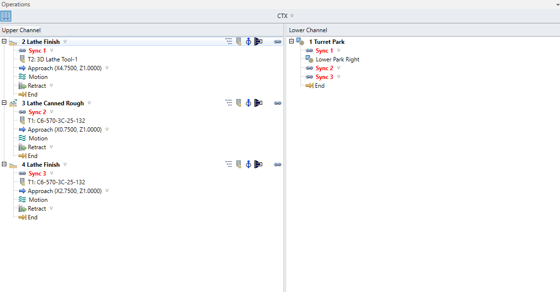
13 minutes ago, scottm085 said:
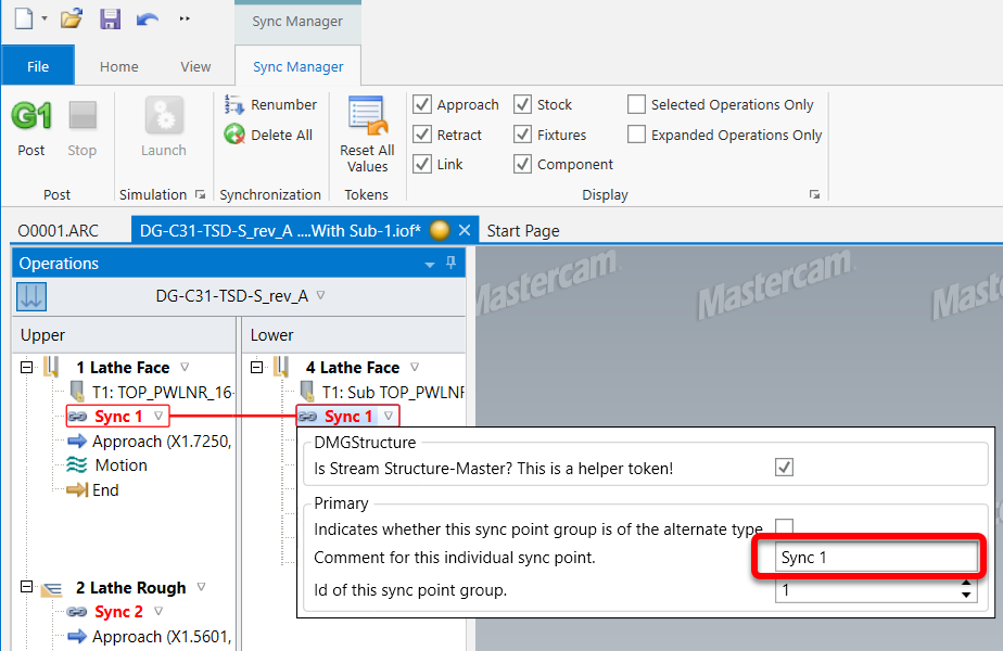
Regarding the comments, it was taught to me by a DMG tech, that for the paths that work on the main spindle the comment needs to be "SP4" and for the sub spindle "SP3". For most situations the syncs have to be opposite from one another. In the screenshot i showed the comment for sync 1 on the upper channel is SP4 and the comment for sync 1 on the lower channel is SP3.
Thanks for the additional info!
Again, I'm not a DMG pilot... I just helped a customer out with the Mastercam side, then handed it off, luckily
I know they're quirky machines, especially with that weird canned language.
-
2
-
-
43 minutes ago, scottm085 said:
Here is an example of syncing a simple jaw turning program. Notice that all the operations have syncs.

Yep.
There was a few setup issues on your part (Machine Properties > Job Setup). I added a spindle toolpath for you and added the syncs.
You can download my updated file here: DG-C31-TSD-S_rev_A - With Sub.zip
One thing to note is that each of those Syncs need to have a comment, or it'll give you an error on posting:
-
2
-
-
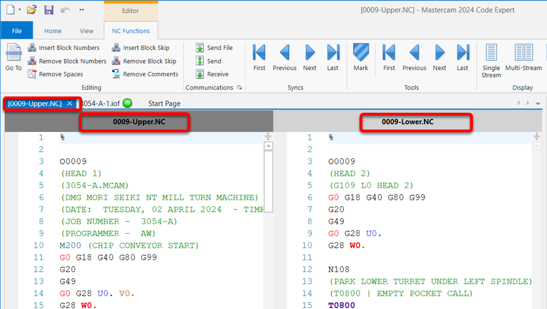
I don't have a CTX handy, but I just did some MT programming for an NTX (to be honest, I'm not sure what the difference is
).
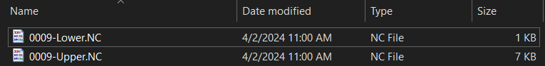
When I posted out the code, it will generate a "-upper" and "-lower" version. For example, here's a file 0009 posted:
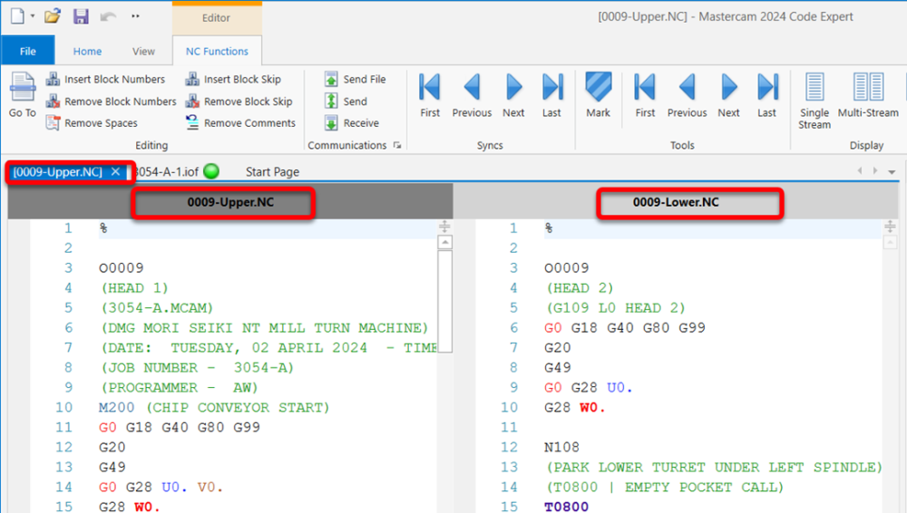
Unfortunately, that's where my knowledge of 'em ends, as I never actually ran one. From what I can tell it was out being output correctly, though, the setup guy/operator I was working with seemed happy enough?
If you could post a sample file (zip2go so we have the machine def), we might be able to help specifically.
You may already know this, but it chooses the "stream" to output based on the individual toolpaths' "Axis Combination" selection, i.e.:
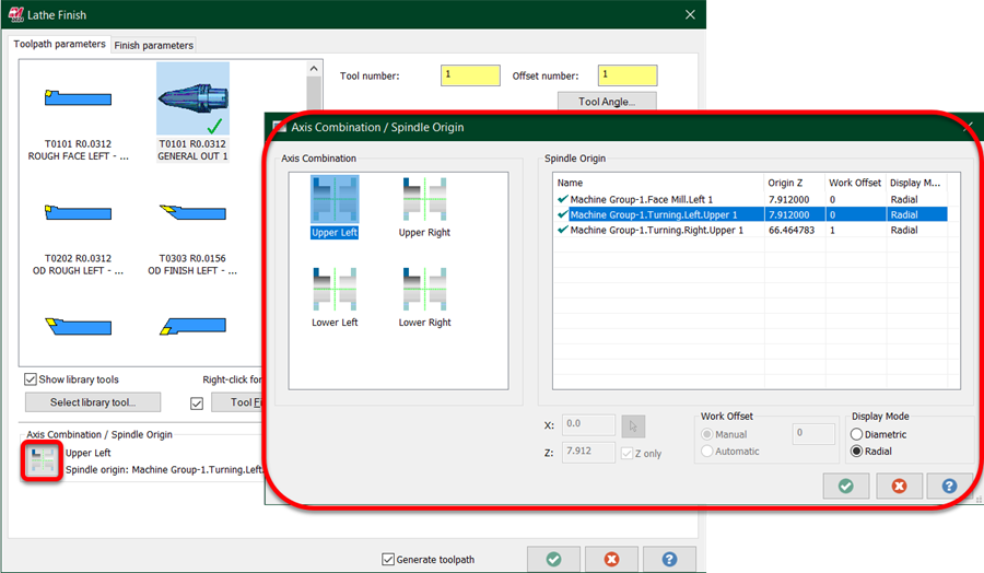
So anything happening on the lower stream has to be programmed to Lower Left/Right. I've seen a lot of old school lathe guys getting into MT forget to check this, as they just set everything up to the Upper Left all their lives.
-
1
-
2
-
-
7 hours ago, bird2010 said:
Hi Aaron...
2024....I don’t have time to switch to English ...sorry!Ah, gotcha, thanks Bird!
Unchecking Check Against In Process Stock (on the Collision control page).
-
12 minutes ago, crazy^millman said:
That toolpath doesn't support undercuts that I am aware of. Do everything but the undercut areas then come with Unified to do those sections. A sample file would be best so someone can teach you a way to get it done.
FYI for all those that might read this thread. The biggest reason I ask for files is to help teach others. I just shared the over 500 different files I have in my Dropbox to students I have been teaching lately. They loved it. #2 is to see if your a legit user of the software.
It is supposed to, as long as you use the offset pattern type. It looks like it's not being enabled correctly? It does in 2022, at least (I had that opened already, so I checked there :)).
-
1
-
-
Undercuts only work when set to Offset instead of Dynamic Type, however, it looks like in 2024 it doesn't enable it at all. Looks like a bug to me? I'd report it to [email protected] with your file.
-
1
-
-
-
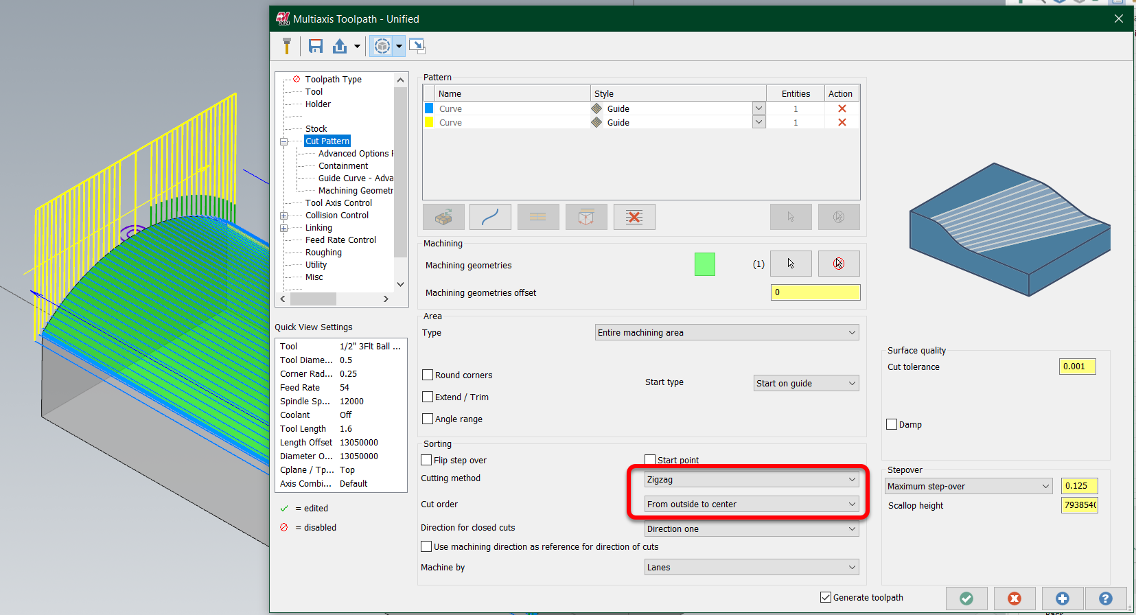
Pretty easy in Unified, so I wouldn't try harder getting it with a 3d if I had 5 axis available, but I admit that I am biased
These are the only two settings you need to make it work:

-
1
-
2
-
-
4 minutes ago, scottm085 said:
Here is what I generally use.
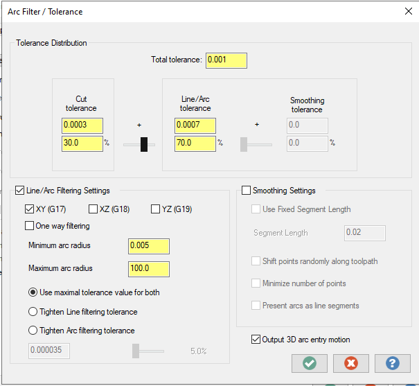
This matches my settings, although I generally enable XZ & YZ arcs as well.
Also, for something like this, a Flowline toolpath works great.
Can mastercam use spindel body to trim or tilt for Toolpath calculation?
in Industrial Forum
Posted
That's not really a concern. The collision detection only works to tilt the tool. Actual motion (the fact that this will cause the B to tilt) is only really a function of the post & machine definition. The part itself is stationary from the toolpath calculation side, which is why when you backplot it (not machine sim!), it shows the tool tilting. If you have the A Axis setup modelled, you can simply select it as part of the Collision Control > Avoidance Geometries selection and it'll be fine.