


Aaron Eberhard
-
Posts
1,404 -
Joined
-
Last visited
-
Days Won
103
Content Type
Profiles
Forums
Downloads
Store
eMastercam Wiki
Blogs
Gallery
Events
Everything posted by Aaron Eberhard
-

cannot calculate are of unclosed polyline
Aaron Eberhard replied to ESHIREY's topic in Industrial Forum
Are you using the Pocketing or Blade Expert toolpath? It would be incredibly helpful if you could provide a file, of course, but it sounds like you don't have either a stock defined nor a containment. It's possible that you don't have the input geometry selected correctly. -
Looks like perhaps the license file got stepped on/installed to a separate location? Eldar will get you sorted out pretty quick I'd imagine.
-
What will be the best 5th Axis Toolpaths for this part?
Aaron Eberhard replied to XLAZY-'s topic in Industrial Forum
That's a fine way to do it (although I'd switch One Way to Spiral..). What's the production qty looking like? It might be worth doing it with two tools, a larger ball mill to do most of it, and only using the small tapered tool to do a few passes right at the end? -
Informal Poll: Who here has defeated the ribbon?
Aaron Eberhard replied to volitan71's topic in Industrial Forum
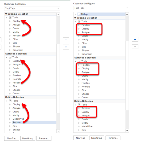
This is my workflow as well. Some projects feel like I'm stuck on the Wireframe tab, most projects I barely touch it. You may just not like the Tool Tabs, or, at least, the default config of them. You can try turning them off. Right click on the ribbon somewhere > Customize Ribbon, and turn these off (uncheck them): It might be more useful to you, though, to customize the order that they're in so that they all are the same (to use your example, Transform > Dynamic moving around), you can see that they're not all in the same order, but you can select that group (say, Position) and use the arrows on the right side to move them into order. Then, all the common ones (say, Position, Display, Analyze) are always going to be first, with the selection specific ones coming after? I'm going to try this setup now, I haven't done it before Thanks for asking the question to make me think of stuff like this!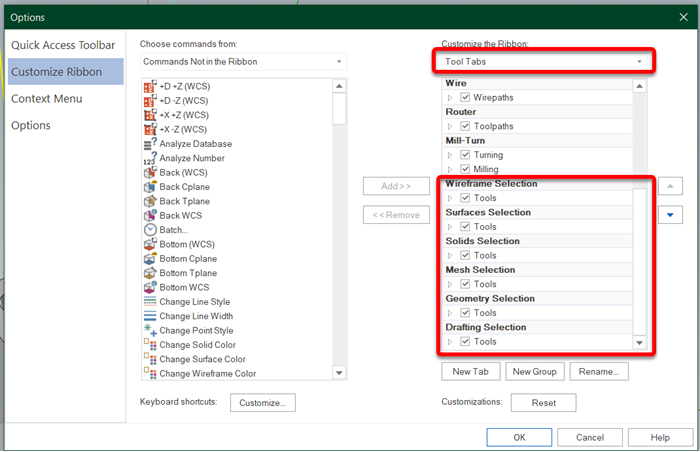
-
Smallest clearance 90° Right Angle Head?
Aaron Eberhard replied to Aaron Eberhard's topic in Industrial Forum
Oh man! I forgot to check MST's website. That makes perfect sense. Thanks! I love their tool holders. -
Smallest clearance 90° Right Angle Head?
Aaron Eberhard replied to Aaron Eberhard's topic in Industrial Forum
No, but if you copy/paste the text it does -
Smallest clearance 90° Right Angle Head?
Aaron Eberhard replied to Aaron Eberhard's topic in Industrial Forum
Ooooh, that's good, thanks G! -
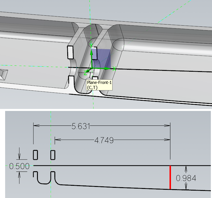
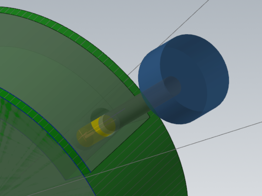
Who makes the smallest 90° head? I've got a feature that I'm trying to help a customer quote in a aerospace part (shocking!) that's a real PITA, only because of space restrictions. The machine itself is a standard Mazak 5 axis w/ a Cat 40. I've went through my normal tooling catalogs, and it seems like the Kaiser/Big Daishawai BCV40-AG90-13-120 is the winner, at 25mm of clearance from the bottom of the housing to the centerline of the tool, but that'll mean I'm still hanging a 1/2" drill bit at least 5.75" out from this little thing. Most of the other heads have at minimum 26mm of clearance, so we'll be hanging the tool out 6+ inches. I don't have tolerances or anything yet, so this is all pretty preliminary, but I figured I'd ask who I'm overlooking. Thanks!
-
To use your car example, though, call up BMW, and see if they'll give you a new ECU for your 2009 325is? If it's NLA (no longer available) as a lot of the 90s/2000s electronics are, ask them to just put in a new model's version. When you ask for the ECU, they'll try to (kindly) tell you that it's no longer made, "Talk to junk yards and see if you can find someone to re-key it for you" (i.e., go try to find someone who switched to a software license that can give/sell you their old hasp). When you ask them why doesn't the 2024 ECU "just incorporate that into the new one so it can work on 15 year old cars?" they'll laugh at you. That's not a practical use case, and it would require tons of engineering to support a very slim "customer" base. X5 is ~15+ years old at this point. Unfortunately, you're talking about jamming a new ECU into it. They started supporting software licenses in the 2019 release, which was made ~7 years ago. The software that powers the licenses now wasn't even in existence when X5 was programmed. To put it bluntly, if you only have a 15 year old version of the software that you haven't maintained, you're not really a customer anymore. I can understand why you're upset, but the reality is that it's hard to justify engineering effort for someone who only buys a product once every ~15 years... Same thing people get told when they try to get BMW to cover a blown transmission in their 15 year old car.
-
Haha, yeah! I showed these guys how to use Dynamic on some wear plates (4140 PH?? I can't remember), either way, took the cycle time from 27 minutes down to like 3... And ended up just letting the stuff pile up and snow shovel it off the floor every half hour or so. You couldn't stand within 10' of it while it was cutting. I hate open machines.
-
Ya never know! You could have been sitting on a gold mine! Well, a $86.25 after shipping gold mine, but still I love when people mod the old cases. I should find a Tandy 1000HX to drop an i9 into....
-
And even when you plan for everything correctly, you can end up with a supply issue of out-of-production parts... That's why you end up bidding against NASA on Ebay if you need 2 or 386 processors nowadays... To answer the original question, maybe if you get lucky Mastercam still has a replacement of one they can sell you directly? Have you talked to the main office in Tolland CT? 860.875.5006 But yeah, if I remember correctly (and it was a long while ago?), I believe that Sentinel was discontinuing the HASPs that were being used. At that time, it looked like USB-A was going to be a fading format anyway, which it largely has been sunsetted except on workstation-class machines nowadays.
-
Wow! Yeah, that's a helluva setup and lot more rigid than the HSK-63A we were playing with. According to HSMAdvisor, at the Helical recommendedations, it'll have .0054" of deflection (which I really don't like), but it'll only be at 101% of tool torque, so, yeah, it seems possible? Also sounds crazy It's also using 1583 lb of force, which is wild! That being said, it's within the realm of possiblities. Depending how long you need the tool to last, I generally try not to exceed .003 or so of deflection, but on a 1" cutter, that .0054" is only 1/2 of a percent... So. Try it? Especially with a Helical enginerd there to provide you another tool if it doesn't work
-
You're welcome, as mentioned above, you can use the same "trick" with Opti. ---------------------- The 2.25" thing per pass is going to be the tough part, I think. I recently did a project in Ti that I was using a ø.75 15FL R.06 Kennametal endmill w/ a 1.5" DOC & 1.5% stepover. Working with a Kennametal apps guy, we ended up at .004 FPT @ 475 SFM (145IPM @ 2419RPM). It worked great on the DA300 they had, as they didn't want the spindle load to get above 30% or so. We were willing to give up some speed for lights-out repeatability, though. The tool life was phenomenal as well. For reference, with this tool, HSM Advisor recommended .01 FPT @ 705 SFM (571IPM @ 3592 RPM!), but that had 752 lb of cutting force. Way too much for the ceramic bearings on that DA to live a long and happy life with! Kennametal Novo's on calculator said to .009 stepover (1.2%) .00325 FPT @ 450 SFM (111 IPM @ 2289 RPM), so we kinda ended up in the middle there in the real world. -------------- The equivalent ø1 from Kennametal only does 2.0 DOC, it's https://www.kennametalnovo.com/app/en/search/kennametal/productdetail/7078249/full Remember that the 100% sliders on HSM Advisor are for a "good machine/workholding/tool holding." If you feel that you're getting lower than expected feeds & speeds out of it, on a better machine/workholding/tool holding, you can absolutely slide those things up. I've programmed a few Okumas with RegoFix using the sliders set at 160%, worked great. Just remember you're putting MASSIVE amounts of force into the cuts
-
You're welcome sir. You can do the same thing with an Opti toolpath in 3 axis, as they're really both just volumetric removal tools. The only thing that trips people up is that they try to drill too small of a hole (the tool can't plunge and then start its programmed stepover) or they use a 118° drill bit, and leave a "cone" at the bottom. The software will see that, recognize that it can't plunge the tool into that and then go back to "it's a full block" mode. That's why I prefer to use a Helix with the tool I'm going to be roughing with as I know it'll fit in the hole it makes
-
Right, there's no way to force it inside of the toolpath parameters. You can, however, leverage the fact that it is stock aware to cause it to drop into a position you'd like. Create a Helix Bore (or drill, or whatever you want your entry to look like) at the specified entry point, then, make a stock model. Pocketing will use it to drop into: Video showing it in action:
-
Yep, I didn't show it on the screen (my bad!) I only put it in the comments on the video... On the toolpaths type page, add those to the "avoidance geometry"selection... Then auto linking should work fine.
-
Mastercam 2024 leaves quadro GPU unused
Aaron Eberhard replied to Johnsp's topic in Industrial Forum
Mastercam will use the graphics card for certain calculations during HSM (High Speed Machining toolpaths) such as Opti, Waterline, Equal Scallop, etc. via the OpenCL (note: C, not G) standard If you're benchmarking programs using the GPU, look for GridComputeServer.exe, as that's the process that handles the GPU utilization: https://my.mastercam.com/knowledgebase/opencl-troubleshooting/ In practice, the calculations being done on the GPU are so trivial for it, that you have to be really logging a lot to notice a blip. The first question people have about using GPU processing is "Why aren't you doing ALL of the calculations on the GPU then!??!?11" The truth is the majority of the time savings of using the GPU for stuff like this is taken up by the operational overhead of managing the data and handing it back and forth from the GPU. -
Instead of editing the jump heights, try using "automatic linking" on the Linking page.. It's more betterer.
-
That's correct.
-
No, unfortunately the G40/41s don't survive the conversions. In the background, a converted toolpath is stored as a 5 axis path (G11s in the NCI instead of G1/2/3), which doesn't have support for comp on/off.
-
Sorry G, Dylan called it.. Time to set up a drip feed for your dinosaurs Here you go, sir:
- 39 replies
-
- 12
-

-

-
Another way to do this is to use Convert to 5 axis, then use a Feed control Zone on the inside pockets to slow it down. It'll work volumetrically, so any changes to the input toolpaths will be instantly updated. I can grab a video tomorrow if it would be helpful.
-
Operation requires planar chain set ???
Aaron Eberhard replied to RandleXX's topic in Industrial Forum
Ah, yeah, you're doing complicated stuff there The only thing I could think of to do with a shape like that would be to create a surface on each individual shape (like, each pedal) using Surfaces > Power Surface. Then, convert that into a sheet body solid ( Solids > Solids from Surfaces). Finally, you can use Solids > Thicken or Model Prep > Push/Pull to make it thicker. Finally, you can boolean those away. But the real question is why do you need the solids removed? Just to learn how to do it? I'd toolpath directly off the wireframe you have in your image for actually cutting the part. -
Operation requires planar chain set ???
Aaron Eberhard replied to RandleXX's topic in Industrial Forum
This means that the chain (splines/lines/arcs) are not on a single plane. You have to have flat geometry to extrude a solid. The commands above have morphed into Wireframe > Project in the years since this was posted originally. If you're trying to wrap something around around a solid shape, you'll need to use Sweep instead of Extrude, though. Post up a file and someone can probably point you in the right direction.