Aaron Eberhard
-
Posts
1,406 -
Joined
-
Last visited
-
Days Won
103
Content Type
Profiles
Forums
Downloads
Store
eMastercam Wiki
Blogs
Gallery
Events
Everything posted by Aaron Eberhard
-

did not show in verify or backplot
Aaron Eberhard replied to cherokeechief79's topic in Industrial Forum
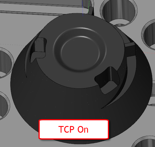
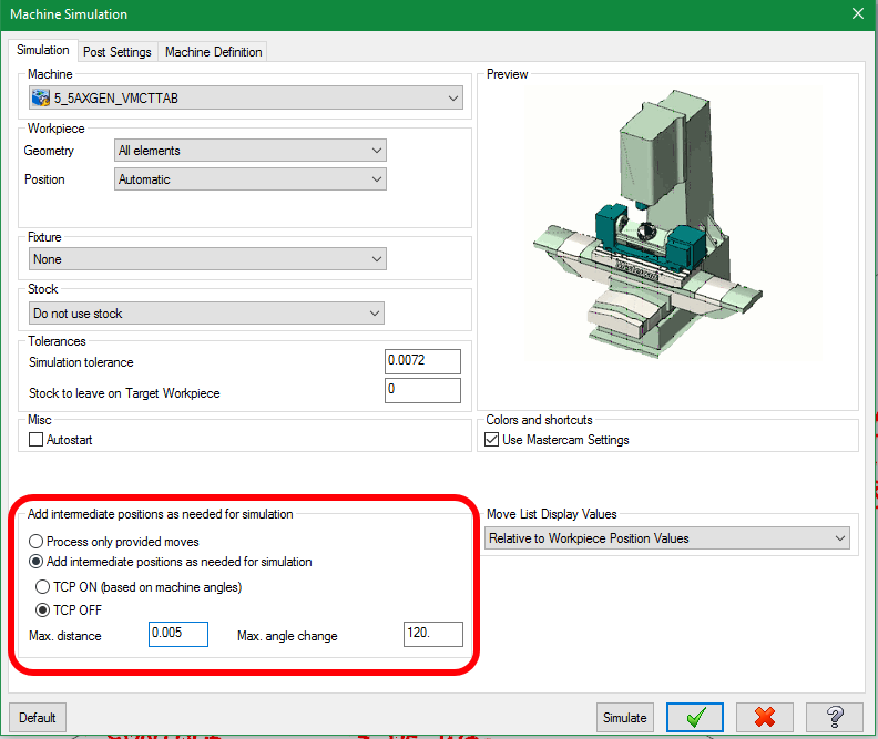
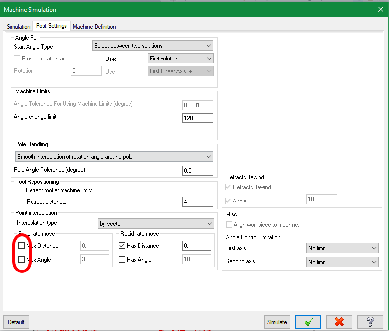
Hey Jim, Just a note that might be helpful in this situation. You're most likely right that it's a singularity issue, and of course, on a machine with real TCP, you don't care too much, but it can cause some big havok on those older machines without it. The problem is that MachSim (by default) cuts as if you have TCP, so you'll never see it without some sort of G code simulation. Starting in 2017, you're able to simulate what it's like without TCP. For example, here's a part that was ran through MachSim with the default settings: Now we turn off TCP (and tell it to guess/fill in moves where there's a huge angular shift, I entered .005 & 120°), as well as turning off the normal "point interpolation" that it normally does to smooth out the display: Let's see if you can spot the differences: Hope this helps someone!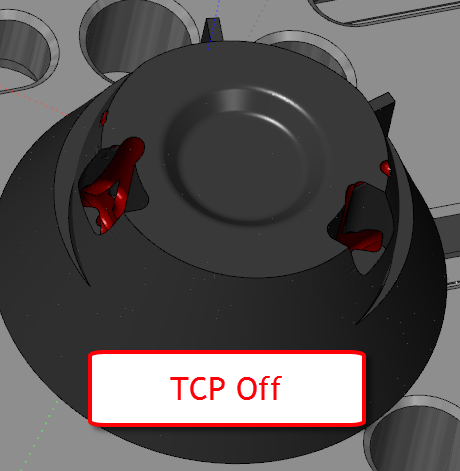
-
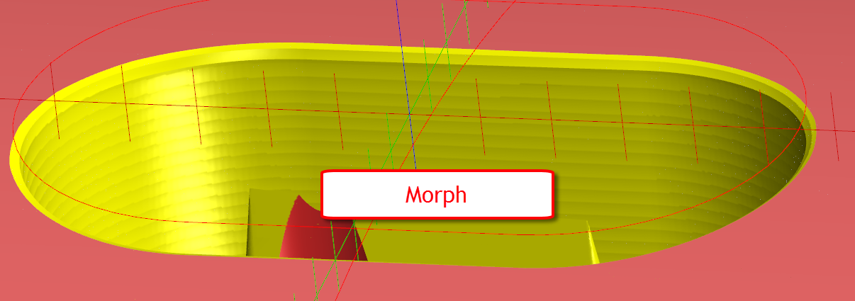
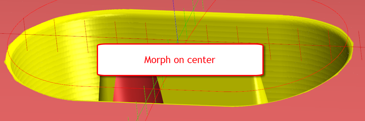
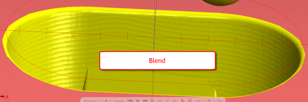
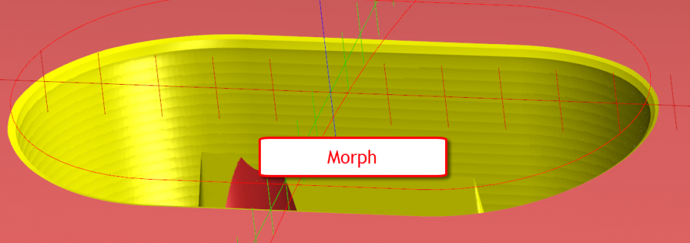
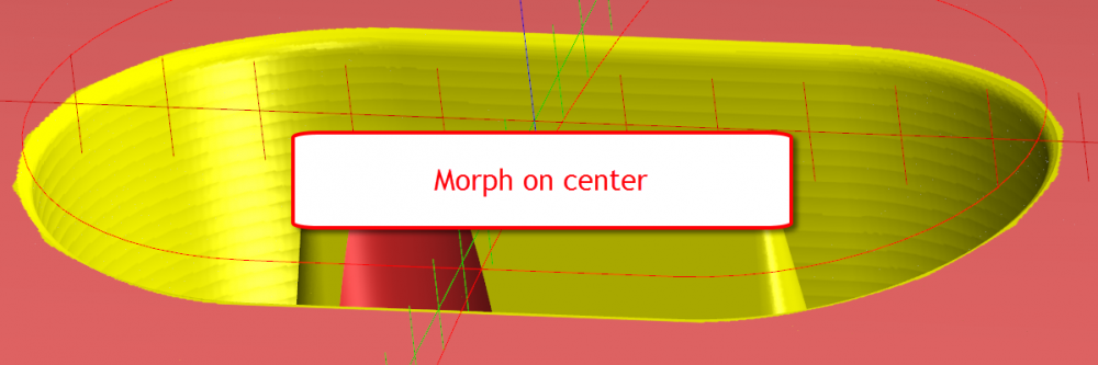
FrankieBoy - You're right that Morph doesn't currently support constant cusp machining, which is really what you're after. Blend doesn't provide it either, as you know, because it creates a 2d toolpath and projects it down onto the surface. I'd like to get that into Morph soon, but that doesn't help you out today. You can get better contact along the fillet if you were to set it to cut with the tip (center of the tool) on the tool axis control page, but then you'll gouge, so head to the collision control page and turn on retract along surface normal if the tip gouges. Here's a comparison of the different options. You can see that Morph is giving you a constant stepover, but not a constant cusp. Compare that to set to Center, and it looks a bit better. Cheers, Aaron
-
For Swarf Milling, it's actually on the MultiCuts page. Look under Tool Shift under Guidance. If you only have one pass, it doesn't make sense for it to be there, I know The cool thing is that if you're doing multiple passes, you can shift the tool down for each pass, so if you're cutting or trimming composites, you don't burn a slot into your endmill. I haven't figured out a better way to interface it when you only have one cut, because then it would be more appropriate on the Cut Pattern page in that case. It's one of those "once you learn it" things for now.
-
Got the file, thanks. I'll put it in the backlog for the developers. The root of is the cylinder instead of plane, but it's only an issue during 3 axis mode. In modern versions, it prevents you from creating the toolpath at all, so this must have been a bit of validation that got added somewhere along the line.
-
Huskermcdoogle - I just noticed this thread, I can't replicate this by creating a triangular mesh with cylindrical clearance zone from scratch in X6.. Can you send the file over to [email protected] or ask your reseller to send it in? Thanks!
-
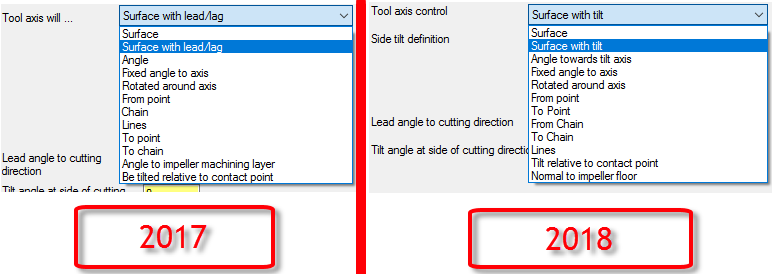
huskermcdoogle - Understandable.. And this is a prime example of where the "intuitive" thing isn't exactly the output that you want. "I just want this to tilt from the surface!" If you were being accurate/honest/not-just-flying-through-the-interface it would be more of a "Well, not REALLY from the surface, like, from the surface but ignoring the parts/motion of the surface that I don't like!" So when it doesn't match your preconceived mental model, that's where the confusion sets in. The really annoying times are when half of the toolpath you want result X, but that's mutually exclusive with the other half for some reason.. So Not a Guru - Because you're using an older version of the software For 2018, we made some minor changes to try to clean up the verbiage/be a bit to be more descriptive: Ron - Always a pleasure to be of service *hat tip*
-
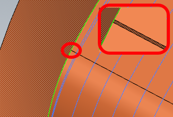
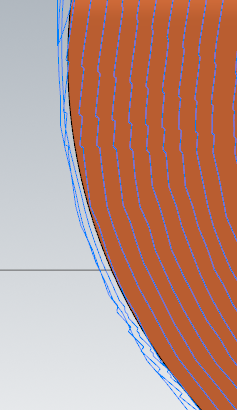
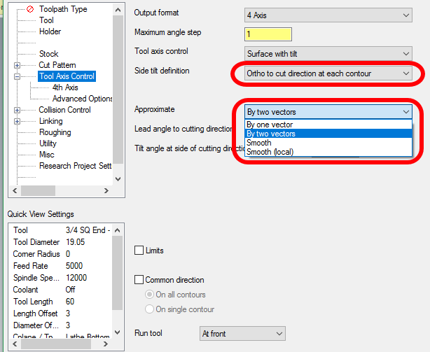
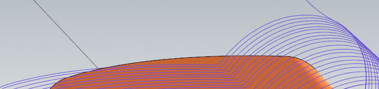
This is a great example of the difference between what you tell the toolpath to do and what you want the toolpath to do Before I get into what's happening, I'll echo that it's kind if silly to run a .001mm tolerance on a surface that has obvious defects: With that being said, the problem actually makes more sense if we loosen up the tolerance a bit anyway. I'm going to turn off roughing and set the tolerance to the default .025 for clarity: There we go. Now, what can we tell from the large stepping here? This is a side effect of telling the toolpath that it HAS to cut with the front edge of the tool while being absolutely perpendicular to the surface at each vector. What's happening here is because of the input shape, it has to slide left/right as it cuts around, which means that you have some correction that has to happen as your tool contact point shifts. And, because I always love to state the obvious when troubleshooting, we can tell that it's definitely related to this because if you turn off the Tool Axis Control > Run Tool At Front and just be perpendicular to the surface the toolpath looks fine (but then is cutting at the center/tip, not optimal). But it's always important to isolate the cause Now, onto the solution. There's a few things we can do to remedy this such as turning off force front and putting a bit of lead on the tool, but to retain the optimal cutting result, front cutting, we're going to have to change how we're getting the tool axis control from the surface. Currently it's set to be absolutely perpendicular to the surface at every vector. There's no flexibility if the surface changes, shifts, curves, has rips/tears/etc. The old axiom of "be careful what you wish for, you might just get it" comes to mind.. If you set the surface control to Surface with Tilt, we start get some options about how firmly it has to follow the surface shape. In fact, one of things you can do is to choose to take the entire contour into account instead of thinking of each vector as an individual point. Once you set that, a whole 'nother set of options opens up as far as how to deal with axial changes within each contour: For this particular example, either general Smooth or more localized Smooth by two vectors will fit the bill. Here's smooth by two vectors: Hope this helps! Edit: Apparently pasting images into the response doesn't actually upload them like it appears it will..
-
Good morning, Sams. Sounds like the kind of thing that Multiaxis Roughing would be perfect for, and you can choose to do a Dynamic style path or an Offset style one, which is often important for an "art" piece The only trick is the boundary has to be surfaces, so if you only have wireframe pockets on a sphere, you'll want to create a fence from the wireframe.
-
5ax drill for spot drill multi size/depth holes
Aaron Eberhard replied to jlw™'s topic in Industrial Forum
If'n you're using Multiaxis drill in 2017 or 2d drill in 2018, you could always just point at your stock and tell it "calculate depth from the top of stock" (it's on the linking page) without creating geometry. -
I'd agree with those guys. Go with a Morph, set your tool axis control to "fixed angle to axis" (that will make it a "3 axis" toolpath), then under collision control, set it to tilt to avoid >automatic on all of the other surfaces (this will let it tilt when it needs to). Turn on roughing options of your choice. Ron touched on some of the Multiaxis thought process, but I think he may have made it a bit more difficult than it needed to be. He's completely right on the first point, you need a good floor surface, the toolpath will only be normal to that surface. Then, everything else can be wall/check surfaces. Generally I don't create any geometry to drive it unless I need a 3d containment to keep it one area or I'm trying to pocket something that doesn't have a floor surface. You can change the stock input if you want to control height or areas being attacked. The real trick to it is to think of it as a question of "what volume do I need to remove?" Give it stock, once it knows that, it'll slice relative to the floor surface using the wall & check to generate the slices. For visualization, think as if the floor was where water would flow. If you poured water on it, where would it run out? If there's a low point or inconsistent wall perimeter, you had better plan on giving it stock.
-
Hmm, I can't find it.. I think it was hosted by GotoMeeting, but those webinars expire after a year. This was for the X7 release. If you contact your reseller, I'm sure they'd be happy to show you some of the tips and tricks on it. I know ShopWare has a webinar on youtube from X7 that includes it, but it's a general What's New, so it's not too in depth on the Tool Manager itself. Cheers,
-
Feel free to toss it in there and take the credit, Daniel Chipman - There was a pretty good webinar done on it when it was released, let me see what I can dig up for you.
-
Daniel - Well said, sir. Newbeeee - I'll pass it along to the webbie I'm still trawling for pics of V3. I know we have them because I've seen them a few years ago for our 30th anniversary, but I may have to get the marketing folk to help me search.
-
That looks about right. That happened in 1990. There were 4 moves total, from Dad & Mom Summers' house to where we are now, all local.
-
Hah, I thought you guys would get a kick out of that I'll try to dig up some V3 pictures if I can find them. I just went down to display by the lobby where there's a brief history. Here's what's written with a few highlights (transcribed because it's easier than reading from a picture): 1983 - Meghan - Apple IIe (It was named after Mark's daughter, who is now our President. Sort of like the Apple Lisa) 1984 - Mastercam V1 - 10 Seats 1986 - V2 - DOS 1990 - V3 - 1992 - V4 - 10,000 Seats 1994 - V5 1996 - V6 1998 - V7 2000 - V8 - Start of Mastercam Certification 2002 - V9 2005 - X - Windows - 100,000 Seats 2006 - X2 2008 - X3 - Start of Mastercam for Solidworks 2009 - X4 - Dynamic Motion debut - 150,000 Seats 2010 - X5 2011 - X6 2013 - X7 2014 - X8 2015 - X9 - 200,000 Seats 2016 - 2017 2017 - 2018 - Coming soon.
-
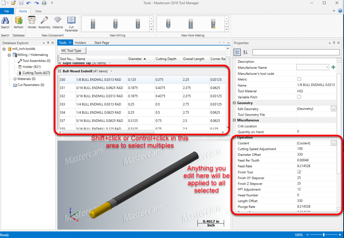
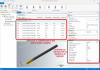
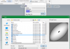
This is easy to do in the included tool manager.. Open the tool database you wish to edit, then select multiple tools, and any parameters that are displayed can be applied to everything selected. If something can't be applied to all tools then it won't be displayed. For example, you have a tap and an endmill selected, so thread pitch doesn't apply to all, it won't be displayed/editable on the right.
-
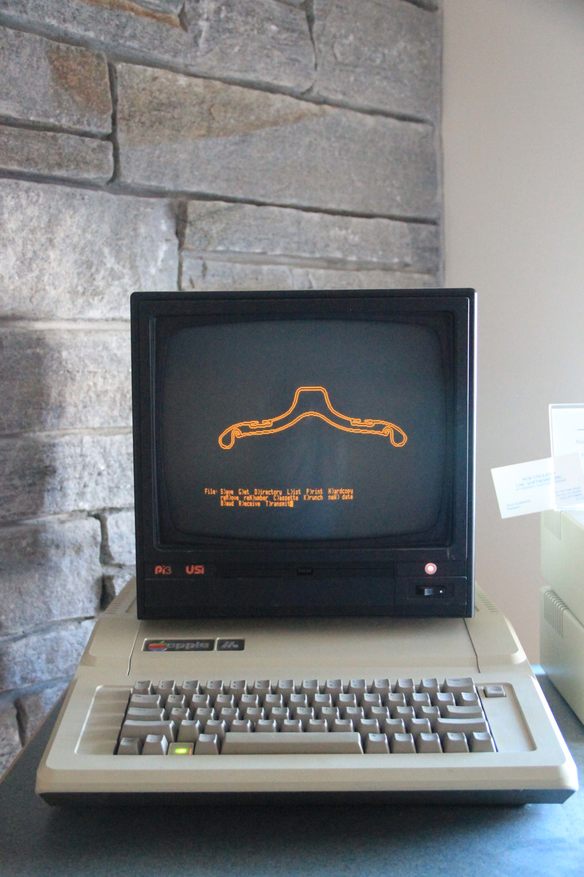
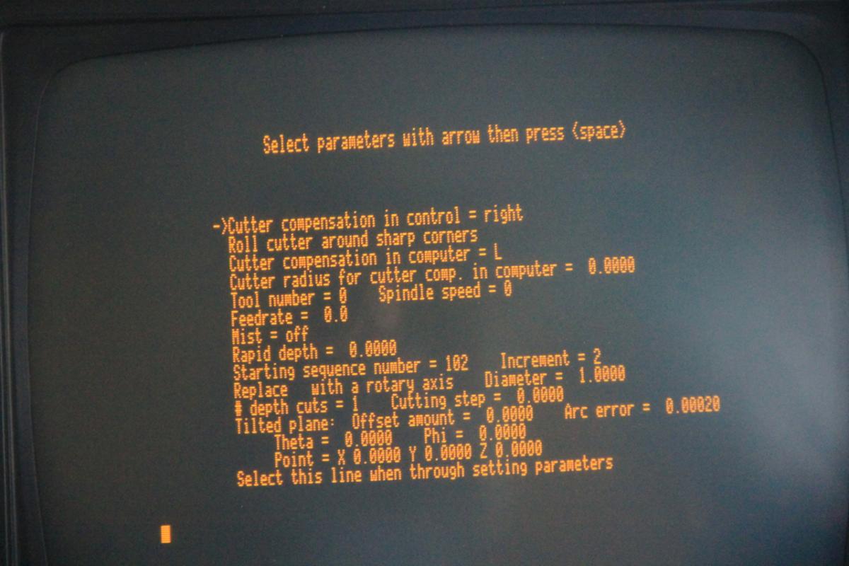
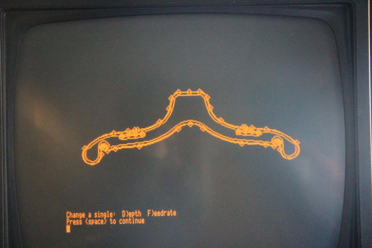
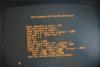
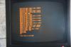
Yeah, I was just trolling through our marketing archive. The first version was code-named Meghan. I'll let you guys see if you can guess why It ran on an Apple IIe. We still have a functional version in our museum downstairs if you ever come to visit. I think we have V1, 3, 9 and the Xes all useable. Here's some "screenshots" of it:


-
draw geometry for G00 rapid moves
Aaron Eberhard replied to Bret Vanderhyden's topic in Industrial Forum
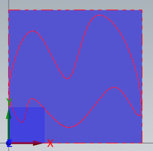
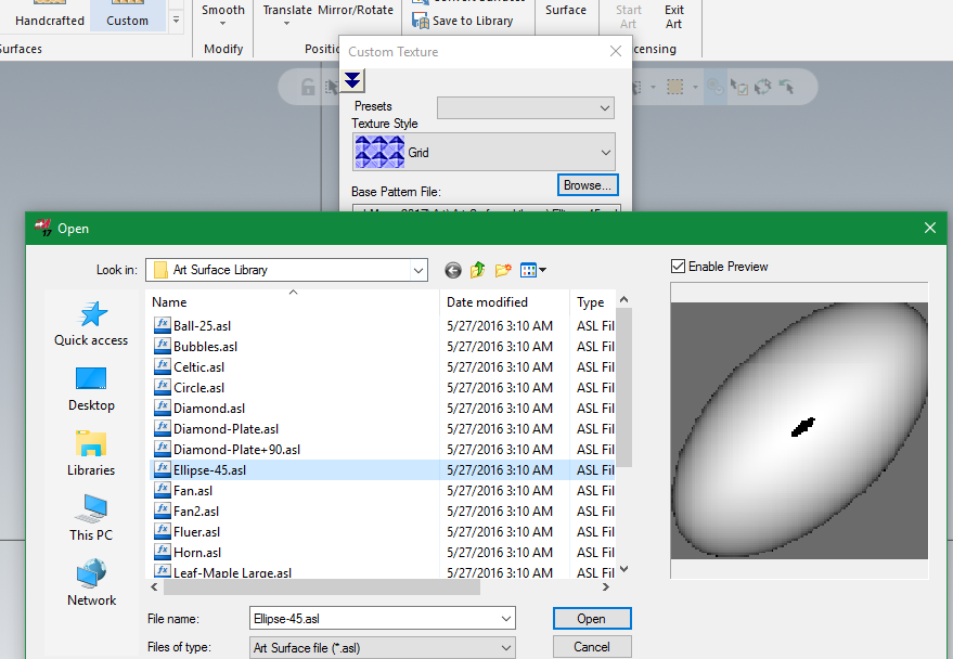
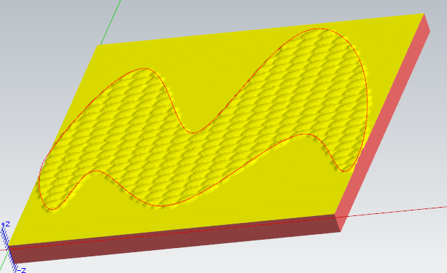
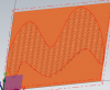
Beautiful artwork, Bret! This looks like a perfect application for Mastercam Art. You probably want to talk to your reseller about a demo on it. The quick version is that you create an art "object" (basically a mesh in the background) that you can manipulate using repeating patterns, importing gradient graphics (white is tallest, black is lowest), etc. to get the size/shape/height you want. Then you can export that to a mesh or Mastercam surfaces. Here's an example of something I created in a few seconds. I'll send you a PM about how to get the file, even a small one like this is ~15mb, so too big to attach here. Start with a area you'd like to fill in (a simple rectangle in my case), and an area you'd like to fill in (the squiggly area in the middle): Then go in and create a pattern (either use a predefined or go with custom). If you go with custom, choose your base image: Finally adjust any settings you'd like to fill in the pattern until you're happy, then right click on the art "object" and choose to Export to > Mastercam Surfaces: Now you can use an ol' toolpath to cut it, I used surface high speed raster here with a basic ball mill just for example: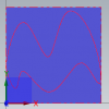
- 26 replies
-
- 1
-

-
- G00
- rapid move
- (and 8 more)
-
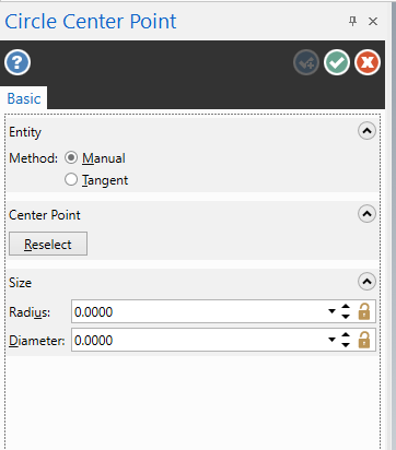
Handy tip: In any dialog like that, you can hit the ALT key to show you what the keyboard shortcuts are (they're underlined). In this case, ®adius was only used in a circle/arc.. Everywhere else it was Reselect. Now the shortcut is U (that was the first unused/unique letter in radius).

-
Hello Jaydenn, This was discussed a white ago over on the other forum (Link). Here's what I replied with over there:
-
Right, but unfortunately neither added enough details for me to reproduce it on my side, so I that's why I was asking for more specific steps. A good way to capture video for free is a program called jing, it'll let you record up to a 5 minute video.
-
Hey Terry, I haven't seen anything like that before, nor have I heard any grumblings about it in the halls... Is it possible to reproduce? Perhaps you could record a video and send it into your reseller/tech support.
-
Glad you like it
-
Hey Reko - This is the thing I like the least with the new swarf, and it's really an issue of layout/design: I haven't figured out a better way to do it yet.. What you're looking for is on the "multiple cuts" under "tool guidance." You'll find the shift there. The reason it's under Multi Cuts is because one of the cool features of Swarf Milling is that you can have it gradually cut deeper for every depth (so you don't grind a notch in your tool if you're doing trimming, for example). So if you set it to Gradual for each slice instead of Constant for each slice, you can transition from -.25 to -0.75 over over the course of the cut. The problem is, if I tried to move just the field for a constant shift over to the cut pattern page, then it would be confusing when you do a gradual shift (either one box is on one page, the second on another OR you have a duplicate "to" box both on Multi Cuts & Cut Pattern with all of the fun of 'which one is in control' that comes along with redundancy.). All things considered, it's not really any worse than having it on the Collision Control page like the older Swarf, I guess. Hope this helps.
-
There was a pretty good guide about this that Chris from QC put up: http://forum.mastercam.com/Topic11007.aspx