


kccadcam
-
Posts
788 -
Joined
-
Last visited


kccadcam's Achievements
")


-
Gcode, Don't see anything?
-
Is this Benchmark file still available? Download link is dead.
-
Big Daishowa is awesome.... More like a turbine blade https://www.bigdaishowa.com/en/products/product-accessories/cleaners/chip-fan
-
As Leon82 said, Highspeed pocket works well.
-
Did those files have Machine Groups already attached or just Models? I was merging an X9 file with a UMC-750 Machine Group into a 2021 file with a Haas Vertical Machine Group. Need to do more experimenting with this......
-
The geometry that is being imported has to be saved as 2021 first? So, I have to go save hundreds of existing files as 2021 before importing now? That just doesn't make sense....
-
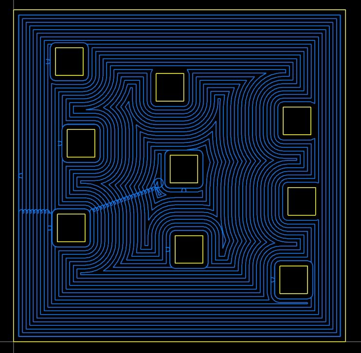
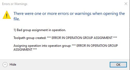
Was waiting on the Update 2 patch before switching to 2021. Got it loaded up and configured. Built some models, programmed the part, then went to merge in models from another file using "Shift and drag" to merge the file into the Mcam window from explorer. (Something I've done thousands of times before) File was saved, then went to re-open the file and now get this with no models now: Any ideas what causes this? Not a good start with 2021.........
-
We have built some common assemblies for the verticals. (most of it is on the fly for each job, we only have so many Cat40 holders) Our Cell system the tool and holder are only saved as an assembly. (permanent unless obsolete)
-
We have built a "Master Tool Library" that is mirrored from our FTS System in the Tool Crib. Evrey tool we have is in there. (over 1400) For the Verticals (Cat40) we just pull from the master, add a holder and go. We also have separate libraries for our cells (HSK63A) and our Brothers (BT30) So, Just copy a tool from the Master library to the Cell library, add a holder and adjust speeds/feeds if nesessary.
-
Not talking about tool stickout,,,,,, Extension holder stickout from a main toolholder...
-
In the standalone manager, You can stack the extension on top of the holder, but you cannot define a stickout length. So, what we do is assemble the holder, check the extension stickout and model the extension to the appropriate length, then marry them together. What we end up with is a multitude of the same extension modeled at different lengths.. Absolutely the biggest mess that CNC needs to address, This halfa$$ sometimes use this manager and other times use that manager to try and define tools correctly is an insane time waster.
-
I joined Dec. 19th 2001............. not sure what number i am Getting old....
-
Makino Tool Data Registration (M449)
kccadcam replied to kccadcam's topic in Machining, Tools, Cutting & Probing
Yeah, that's the direction I'm leaning, I was just hoping we could do it through the Cell controller and not in the .NC code. Not looking like this is possible. -
Trying to control tool wear comp per tool per job on our Makino Cell. Example: 3/8 endmill is Tool#10037500 in our D500, on one part the wear comp is zero, on another part we need -.0005 wear comp. I was hoping you could do that thru the MAS Offset files with G10's but, this is only to assign pallet rotation and location: O7998 (0000-XXX-XXX_OPP-1 OFFSET FILE) G90 G10 L2 P1 X0.0 Y0.0 Z-23.622 C0.0 A0.0 G10 L13 P10037500 R0.0000 (MAS does not allow 8 digit on the Fanuc side) M99 Makino is telling me I cannot do this thru MAS and I have to use M449 (Tool Registration Mode: Type 2) in the .NC program to control this. If I have a 3/8 end mill that is Tool # 10037500 (we use 8 digit tool numbers) Do I have to use the (S) Pot Number or just the (T) Tool Number? And how do I input negative values? Is that what M54 does? Here is my example: % O5000 (0000-XXXX OP1 REV A) (Generation Date = Thursday October 10, 2019 Time = 08:05:16 AM) (Machining Setup = SHIELDS Makino D500 - Pro6 - HSK - 14K Setup) (NC Format = Makino - Professional 6 - [G68.2 / G43.4] - Rev 5.0) (T10037500 .3750_EM-FIN_LOC=1.250_OAL=1.575 Assembly ) (T14025000 .2500_BM-FIN_LOC=.750_OAL=1.300 Assembly ) (T14012500 .1250_BM-FIN_LOC=.500_OAL=.900_NO THRU COOLANT Assembly ) (T18012500 .1250_CM 90 DEG_OAL=.715_NO THRU COOLANT Assembly ) (T12037500 .3750_BNM-RUF_R=.015_LOC=1.000_OAL=1.500 Assembly ) M449 S10 T10037500 (REGISTER POT #10 AND TOOL # 10037500 ) S106 T0005 (.0005 TOOL RADIUS WEAR) .. .. .. N10 T10037500 (.3750_EM-FIN_LOC=1.250_OAL=1.575 Assembly ) M06 T12011800 M01 X11. Y-10. (CUT TOP HEAD CBORES) M11 M13 G00 G90 G54 A-85.38 C158.192 M10 M12 M251 S12000 M03 G68.2 X0.0 Y0.0 Z0.0 I158.192 J-85.38 K0 G53.1 M97 X.8602 Y-9.46844 M08 M26 P1 G43 Z4.30999 H1 <------(HEIGHT CALLED) G00 Z3.30999 Z2.40999 G01 Z2.23699 F25. G41 X.8116 Y-9.52029 D1 F30. <------(CUTTER COMP APPLIED) G03 X.86344 Y-9.56889 I.05022 J.00162 G03 X.86344 Y-9.56889 I-.00324 J.10045 .. .. .. .. .. .. M449 (CANCEL REGISTRATION AT END OF PROGRAM) M99 % Don't really care for this solution....... What is the best way to control Wear comp per job on a Makino Cell? Would it be easier thru Macros?
-
Just do a search for OpenCL in the forum... Lots of info. OpenCL shares the graphics processor for multithreading toolpaths.

