


BrianP.
-
Posts
341 -
Joined
-
Last visited
-
Days Won
25
Content Type
Profiles
Forums
Downloads
Store
eMastercam Wiki
Blogs
Gallery
Events
Everything posted by BrianP.
-
That will work also. Just using your vise jaws as a fixture by adding clamps. I just like all my force to be downwards. If your doing the job ok you won't over tighten it. Give it to an operator all bets are off. 6 of one half a dozen of another. Give this job to 6 people and you will get six different ways of doing it. None of them wrong if the parts come out right.
-
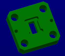
You would end up something like this. And yes you can bolt it down tight enough. If you have c'bores on the back you can make islands on your fixture to locate the part or add 2 dowel pin holes in the center area to locate. Just have an M0 to add center screws before cutting it free. Very light in the vise. I have used an inch pound torque wrench to do delrin parts. Be surprised how light you can clamp when you are just facing and drilling holes.
-
Fixture all the way. Op 1 vise. Drill holes in the middle skim top. Op 2 down on fixture hold with screws through holes. Drill corner holes, mill outside contour steps and posts. Add screws through posts cut center out . Done 2 ops.
-
I had already got job running but I downloaded and tried it. Works like a charm for this application. Can even drive across the top if so desired. Got to remember this one. Thanks
-
If you think your dumb what does that make me? That's what I figured. I knew there was more than one way to skin this cat. It's on things like this that I struggle a little. Never have had any formal training and have never gotten to work with any high skilled programmers. The only formal training I've had is a couple of tech days for a few hours with JP. I will try each one of the suggestions to further my skills soon as I get some cycle time going.. Thanks.
-
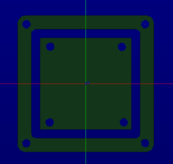
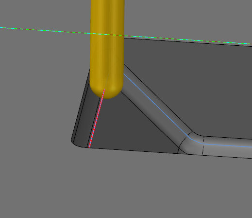
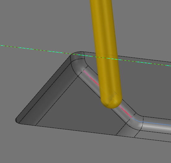
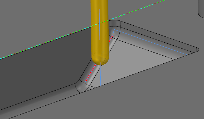
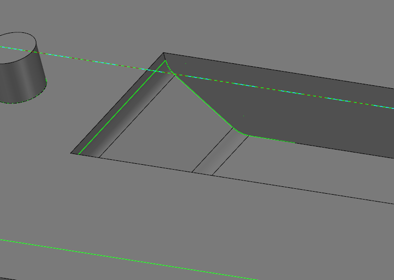
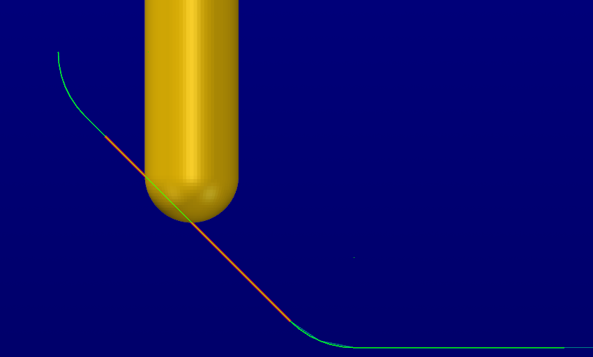
So every time i try a simple 3D contour up and angle the tip always drives through the wall. I usually manipulate the geometry little by little till I get the desired result. Kinda frustrating and time consuming. Got to be an easier way but damned if I've been able to figure it out. Just want to be able to drive up and around to give a good finish along the walls after surfacing the angle. Any help would be appreciated. TIA. Edit: 2018 with only single surface and no multi axis tool paths available.
-
If you are not using one try a pipe tap reamer before tapping. Will make a huge difference in the torque needed to tap.
-
Manually set it to a 1 to enable it. Turn setting 7 to off. Estop the machine. Change 0 to a 1 and you should be good to go if your machine is capable. Turning it on and off keeps the spindle from having to orient every cycle. Edit: It is standard on some models from the Haas web site. Just need to turn it on.
-
Double check that rigid tapping is enabled by going to parameter 57 and look for rigid tap and be sure there is a 1 there. Curious as to why you are peck tapping every .03? Material? I rigid tap in Haas all the time and never an issue.
-
Jamie from CNC Systems helped out. I posted my version number and it is exactly what you thought. Wrong version. I had thought I did download and reinstall once the public release came out but I guess not. My bad.
-
I think I did that but it was longer ago than yesterday so I don't remember. I will try a clean install as it now is becoming an issue with trying to open newer Solid models from engineering. Before this is was just a curiosity. Now its a PITA. Thanks
-
Your alt+z will still work like you want. Just undock you levels manager from the operations manager. Right click the tab for levels and check floating.
-
If have 2018 installed and have been running it since release. I also ran the public beta releases. Every time I do an update check it tells me no updates available yet I have never installed a single one. If I manually download the updates and try to install it still will not do it. Any one else have this issue?
-

Center on entry point for simple pocket not working
BrianP. replied to danielm's topic in Industrial Forum
Try putting X/Y clearance to zero. -
Yes you can assign a hot key for it. Right click tool bar>customize the ribbon>key board shortcut>home Scroll down to more colors. There are 3 of them one for wireframe, solids and surfaces I think. The second one should be for wireframe. Assign a short cut key and you should be able to change colors on the fly. Worked for me. Edit: You can also preselect any feature wireframe, solid or surface use your shortcut and choose a new color and it will change it.
-
Response from Vermont Gauge tech support. Emastercam tech support spot on again. Wall Chart CYL-THD Final 8-15-11 2.pdf
-
Thanks. That is what I thought seeing as the 3B is the tighter tolerance. Just was not sure if common sense ruled with pitch diameters.
-
Quick question. Can you use a 3B gauge to check a hole toleranced for 2B? Specifically the no go. Print calls for 3/4-10 2B we have a 3/4-10 3B gauge.
-
Compensation Poll - Take the poll
BrianP. replied to Matthew Hajicek - Singularity's topic in Industrial Forum
Some one stated it perfectly in the other tread. When I wrote code by hand it was basically "control" so you could just type in actual numbers for milling. X0 was X0 not X.25 or whatever. Since going to Mastercam for programming its always been wear for me. I can do the math if I need to figure out something but why in this day and age would you be reading lines of code. I just let the program do all the work. Although it is eye opening how much work it use to be when I do something quick in MDI. I think back to how much code I use to type in by hand and I wonder how I ever stuck with it at all. It was a lot of work. -
I was going to say what do you mean going?
-
Yeah. Everything is +/-.001 and true position of .002-.005. Even the clearance holes for screws. Frickin engineers.
-
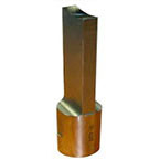
Here we do a ton of flanges for microwave applications. Usually we get away with being able to put a .015 radius in the corner but one customer is insisting on .008 max. The parts are over .200 thick so I'm thinking a .016 endmill over 10x diameter might be a small challenge and time consuming. Our Haas VF2 has the spindle orient option so I can program it to orient at any angle. I would like to broach the rectangle to size while forming the corner radii. The size is pretty small .140 X .280 with a +/-.001 tolerance. I would mill the slot to with in .003-.005 with a .047 endmill leaving a .0235 radius in the corner to broach out. Has anyone done anything like this? I have seen a bunch of keyway broaching while researching this but nothing really like the application I am looking at broaching a rectangle. The feature is through and the material is Aluminum. Thinking about something like this custom made for the size we need. Place to purchase?
-
I absolutely abhorred 2017. Ran like chit for me. 2018 runs much much smother. Now I just hate it. ( still think the interface is chit) I would definitely update to 2018.
-
If you are transforming ops the ghosted ops need to be "unghosted" before renumbering. I have had this problem and was quite frustrated till I figured out what was going on. Otherwise try renaming your NCI file. You don't actually have to rename it just go to rename NCI and click green check mark. This works in many cases.
-
Drill Linking Parameters Not Working ??
BrianP. replied to CADCAM3D5AXIS's topic in Industrial Forum
I believe retract needs to be set to incremental. Then you will post out with a G98 and an R of -1.1


