BrianP.
-
Posts
341 -
Joined
-
Last visited
-
Days Won
25
Content Type
Profiles
Forums
Downloads
Store
eMastercam Wiki
Blogs
Gallery
Events
Everything posted by BrianP.
-
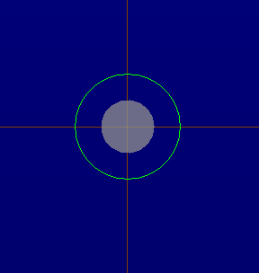
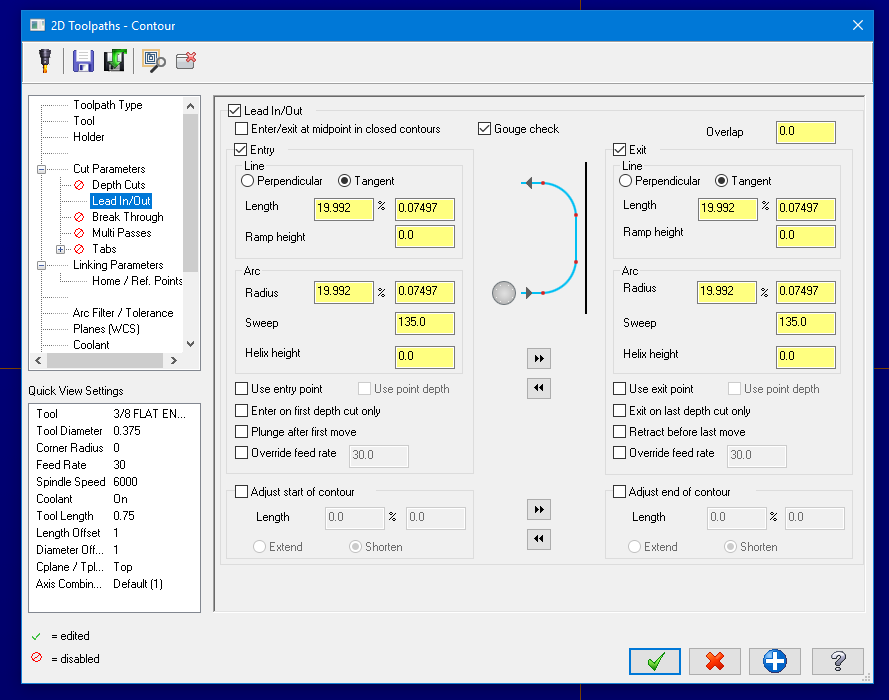
After a little more thought and research the formula that should work is take your tip dia. + your tip offset X 2 and use that for your diameter. So on a half inch hole with a 1/4 chamfer mill with a .06 tip amd .03 tip offset you would have: .06 (tip dia. in tool definition) +.06 ( tip offset x2 )= .120 .500 -.12 = .38 / 2 = .190 * .4142 = 0.078698 That in your line and arc with 135 sweep will hit the center of the arc. Tried it for 3 different tools and worked for each.
-
Simple. Post out your program and with a little manual editing no problem. Haas using an A axis just add another address to your X and Y line whatever you want to be at. Cutter comp off. Lead in lead out line only no arc. Original output using 3 axis post. G0 G17 G40 G49 G80 G90 ( 0.125 CHAMFER MILL ) T1 M6 G0 G54 G90 X.0625 Y0. S6000 M3 G43 H1 Z.1 M8 G1 Z-.03 F30. X0. X-1.4313 X-1.4938 G0 Z.1 M9 M5 G28 G91 Z0. G0 G53 G90 Y0. M30 Modify first line for A axis G0 G17 G40 G49 G80 G90 ( 0.125 CHAMFER MILL ) T1 M6 G0 G54 G90 X.0625 Y0. A0 S6000 M3 G43 H1 Z.1 M8 G1 Z-.03 F30. X0. X-1.4313 X-1.4938 G0 Z.1 M9 M5 G28 G91 Z0. G0 G53 G90 Y0. M30 Copy and paste and edit to do more passes. G0 G17 G40 G49 G80 G90 ( 0.125 CHAMFER MILL ) T1 M6 G0 G54 G90 X.0625 Y0. A0 S6000 M3 G43 H1 Z.1 M8 G1 Z-.03 F30. X0. X-1.4313 X-1.4938 G0 Z.1 X.0625 Y0. A45. G1 Z-.03 F30. X0. X-1.4313 X-1.4938 G0 Z.1 X.0625 Y0. A90. G1 Z-.03 F30. X0. X-1.4313 X-1.4938 G0 Z.1 X.0625 Y0. A135. G43 H1 Z.1 M8 G1 Z-.03 F30. X0. X-1.4313 X-1.4938 G0 Z.1 M9 M5 G28 G91 Z0. G0 G53 G90 Y0. M30 And on around till done. Don't forget the decimal point after A address or you will only get a percentage of a degree. A90. will be 90 degrees A90 will be .9 of one degree. Edit: Noticed the Solidcam addition to subject if Mod wants to delete thats fine with me.
-
It's a formula that some one figured out a long time ago. The only thing Jeff forgot was a 135 degree sweep for angle . So for a .737 hole using a 3/8 endmill it's .737-.375 =.362 / 2 = .181*.4142 = .0749702. That is your lead in lead out for line and arc with a 135 sweep you will always go to center of a hole. Also handy for slots and a few other things where your sweep is tight. A little math for a 45 and you can bang it right on center or at least within a minuscule amount that your operators should be comfortable.
-
Mill guy now for many years but I did a bunch of manual lathe stuff back a ways ( not saying how far back). So long as you don't hit the ways it's good to go. Might need some special jaws for holding or something and pay attention to your spindle speed. Did a lot of funky stuff. Here is one I did . Leveled it up. Chucked it in and clamped on some counter weights. Was for a 600 ton crane. Weighed I think around 600 lbs. Cleared the ways by thousandths lol.
-
I just select the tap I want from the metric data base. Change feed rate to whatever I want and Mastercam will do the math. Select an M3 x .5 tap while in inch. Change feed field to 10IPM and Mastercam automatically changes RPM's to 508.
-
Fissed for accuracy.
-
When I have seen funky stuff happen I have had some success with running the RAM saver and/or doing a rename NCI.
-

Unhide/hide I want to keep geometry- hide surfaces
BrianP. replied to mezzer's topic in Industrial Forum
I tied my blank and unblank to hot keys. When something is in my way alt+b blanks it and alt+n unblank. Solid is usaully on one level and wireframes for each op on others. -
Hey you started it. "The system of imperial units or the imperial system (also known as British Imperial[1] or Exchequer Standards of 1825) is the system of units first defined in the British Weights and Measures Act of 1824, which was later refined and reduced." Oh wait. That's right your French.
-
No. A workaround when you go to print a setup sheet is to change the system origin color to the same as your background. This will "hide" it while you print out a setup sheet. A small pain but will save you the headaches of your operators being confused. Edit: The other thing I used to do is create a quick note with a single leader. F9 to hide the origins and then print. Can put your notes on different level or just blank them so the are hidden. Edit #2: John beat me to it.

-
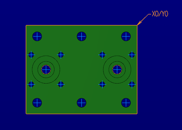
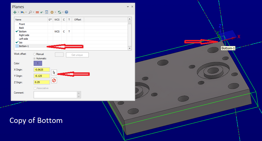
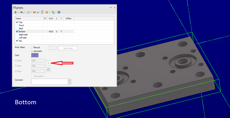
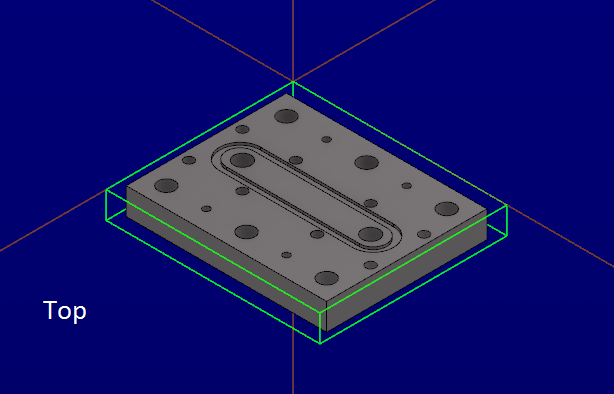
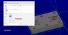
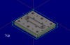
Mastercam system origin cannot be moved but the WCS can. So here is a top using stock corner as WCS. You go to bottom. The small arrow used to allow you to pick a new WCS while the part stays tied to system origin. You now need to create a copy of the view then the arrow becomes active and you can choose a new WCS on the part anywhere. The part never moves from system origin so that when you verify you will get a complete part.

-
No worries I don't think your being mean. There are always 2 sides. I figured it had something to do with the solids needing to be locked in for one reason or another. Doesn't mean I have to like it.
-
If I was closer John I would come work for you. Might make it fun again learning new stuff. I always want a job where I am the dumbest so I can learn and go to a new level. Unfortunately around here most shops are small job shops and the programmers are fair. Usually end up teaching many tricks and features of Mastercam to people. Edit: Oops. Now I'm the braggart.
-
Yup your missing something lol. Only first op is top. After that I would use bottom, left, right, front and back. Was always able to select work origin in each with a mouse click. Now you have to copy the view to be able to select something other than Mastercam origin. All ops verify to make a complete part.
-
Braggart. Job shops are usually vise or fixture held parts ( plate work ) most of the time. Do get some trickier parts that take a while to fixture but nothing that complicated. If I took a week to figure out a part I would be looking for a new job fast. It is all about what we do.
-
I don't understand. Break this habit why? I can import a file orient it move it to origin and be programming in less than a minute. In many cases maybe 30 seconds and I am programming away.
-
Well kinda. Aren't all machinist borderline OCD lol.
-
Realistically you can modify top by orienting the part the way you want op1 to be before you start. I use 3D translate and move part to origin. Unless your part comes in at some weird angle couple of clicks all done. Used to be able to have 6 ops and never have to create a plane. Now after first op have to copy everything so you can pick a part origin. Instead of a nice clean planes manager you now will have 8-12 planes for simple parts. Drives me nuts.
-
Is 2017 faster for you?
BrianP. replied to Matthew Hajicek - Singularity's topic in Industrial Forum
Still slogging along with it. Still find it very cumbersome and frustrating. So many things that I used to be able to do faster now take longer. Opening recent files is a pain. click on the down arrow hover pointer over folder icon and wait for drop down. Changing colors and levels right click no longer works. Escape key on some functions does not work any more. Planes manager starting in X9 to me is horrible. Used to be able to orient part in top view then use bottom, left, right, front and back for next ops being able to choose where origin is. Now have to create a copy before being able to select an origin other that system origin. The last 2 shops I have come into starting the milling departments and recommending Mastercam. Always have thought it was great and easy to use regardless of small bugs. In a program this huge you got to expect somethings to be missed. That being said I think I would have a hard time being adamant about Mastercam again. Would be much more willing to try a different Cam package than I was in the past. JM2C -
He is the Trak guy here and been here longer than I have. Good guy to work with. Does some really nice work. But very opinionated on many things. Not even going to try and change his mind. Have to agree with the inspector from the customer though. I would never make a part like this. .067 is the UPPER limit. .0671 is oversize.
-
That's how I have always interpreted it. 067 is the high limit .0671 is out. You cannot put a .067 pin into a .067 hole. Size for size would be press fit. Link to other forum. http://www.cnczone.com/forums/machinist-hangout/318552-machinist.html Last answer is spot on. And I've never even gone to school.
-
OSG Drilling Cast iron at .022" IPT
BrianP. replied to Rstewart's topic in Machining, Tools, Cutting & Probing
My sphincter clenches up just watching that. Holy chit. Impressive is an understatement. -
Seen this on another forum and now I have run into it here. You have a hole say .066-.067. A .067 pin goes in the hole but an .068 does not. Guy says good. I say no good a .067 pin should not go. For sake of discussion we will assume an exact size not a plus or minus pin. I believe his thought is you get to use up to .0679 and it is still a .067 hole. Not bad till it actually goes to .068.
-
I was thinking 3D contour also. These grooves are only for air to flow through. Nothing fancy needed.
-
Correct.