Colin Gilchrist
-
Posts
7,769 -
Joined
-
Last visited
-
Days Won
162
Content Type
Profiles
Forums
Downloads
Store
eMastercam Wiki
Blogs
Gallery
Events
Everything posted by Colin Gilchrist
-

Micro Programming In post
Colin Gilchrist replied to vikc's topic in Post Processor Development Forum
MP supports a lot of options. Macros? Sure, depending on what you want to do. "Micro Machining" using small decimal values? Sure, it can support that also. You can support up to 9.9 digits (9 decimals before, and 9 decimals after, the decimal point.) But the Post must be configured so the XYZ, Feed, IJK (circle center) values (etc.) are modified for more precision output. Plus, you must go in the Mastercam Configuration File (for Mastercam itself), and enable the "System Tolerance", and set the tolerance to 0.000000001. You will (typically) get the most precision on the machine using Metric Mode. Doing this allows you to support Nanometer Precision output. Now, the issue you will also (typically) face, is how does Windows store the number as a floating point unit, and how Windows operates on very small numeric values, contributes to issues with Rounding in the output. You can utilize 'round_opt$' to influence "what internal routine does Windows use to retrieve and round numbers". -
Micro Programming In post
Colin Gilchrist replied to vikc's topic in Post Processor Development Forum
You will need to elaborate on what you mean by "Micro" programming. I have no idea what you are referring to. -
In the example, the geometry of the toolpath is being "manually" created. If this is on a surface, use Surface Finish Project, or Surface High Speed Project. Use "Curves" as input. This is purely 3-Axis.
-
You're welcome. I'm glad that worked. The thing I hope you can see if you examine the Mastercam File I attached > you can use Mastercam to "reverse engineer the G-Code", by plotting the XY points. For the Arcs, on a Haas machine, the IJK values are "relative to the start-point of the arc". This can be easily done by taking the XY position (before the current G02/G03 line), and using Transform to copy that point to the IJK location. Then use "Arc - Polar" to construct the Arc in Mastercam. What I did was to manually draw out the path, so I could visualize the cutter path. When I started building the 2nd path, I could measure that it was offset by 0.015, but by constructing the physical geometry, I was able to deduce that while "x-or-y values have been shifted", that was done by just editing the NC code. The older Leadwell machine was able to ignore the arc errors (likely has a higher tolerance set in the control parameters). So even if the old machinist created all those old programs by hand, you have a very capable tool in the form of Mastercam combined with your mind. I'm a bit surprised that nobody has downloaded the Mastercam File, or the NC Code file. Perhaps people didn't realize there were downloads attached, because they were in the middle of my reply?
-
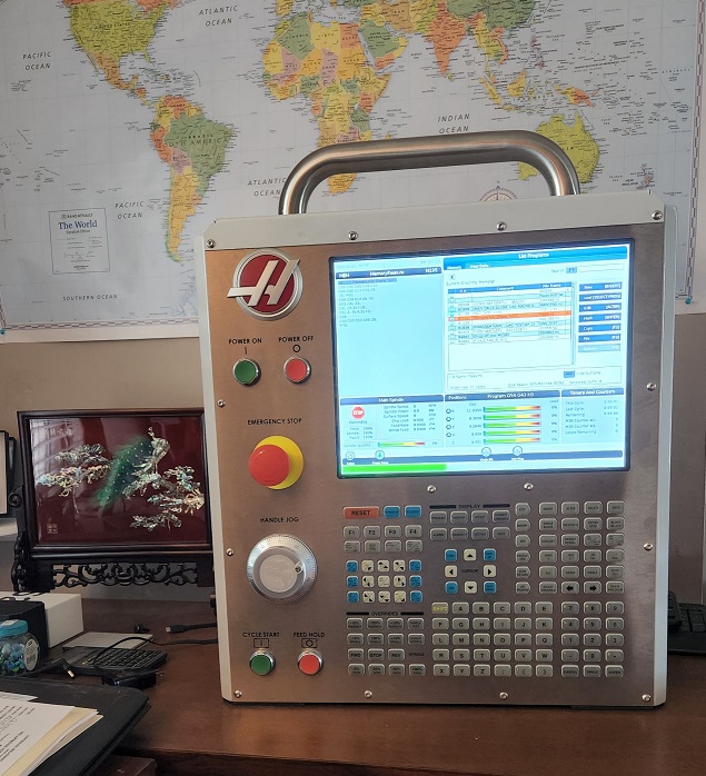
I also have a Classic Haas Control Hardware Simulator, running Version 18 Software (Maincon board configuration). Our Federal Phone Support Haas Guru has multiple sets of hardware boards, from the old Motorola processors, through the cold-fire series, up to the last CHC versions. He can swap out components to configure the Haas to diagnose most CHC issues over the phone for our Federal Customers.
-
-
Hopefully, if you look at my Mastercam File, you can see how I constructed the geometry, and was able to make some assumptions about how the path was originally constructed, so I could fix the issues. There were IJ Center point errors, yes, but also the XY positioning "start points", and even the "entry/exit" lines (point before the Arc Start Point or after the final endpoint (G40) needed to be adjusted, to maintain parallelism and proper tangency. One thing that makes this very difficult, are the changes needed in not only the I-J values (describing the Arc Center, relative to the START POINT), but also the shifting of the "start/end" XY coordinates, due to offsetting an arc that is a "partial arc", where the entry line is not tangent to the arc start point. In this case, you've got to offset, and retrim at the intersections.
-
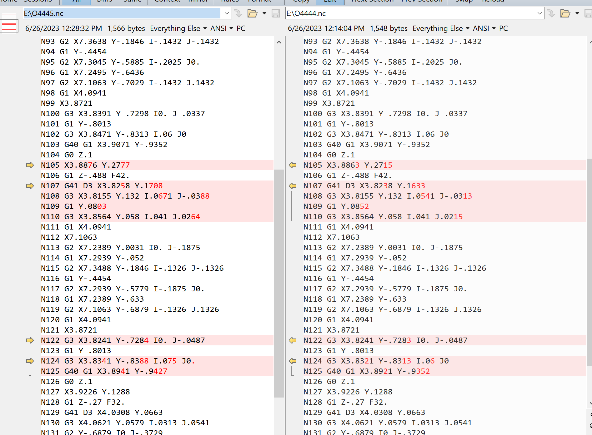
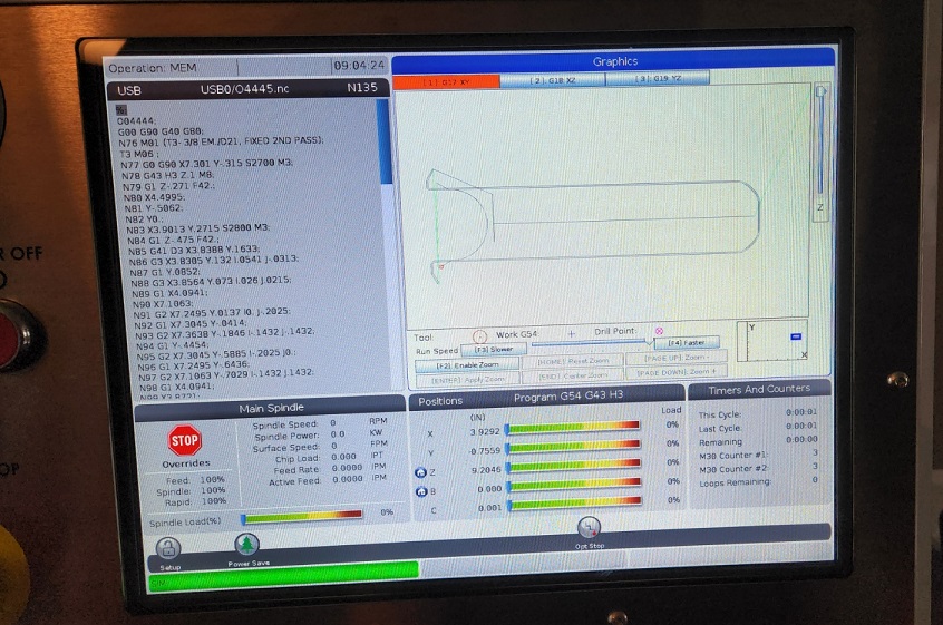
Here is how I fixed this. I went into Mastercam, and I plotted all of the points for both passes. I do this so I can draw lines and arcs, and "try to get an idea of what you're doing". There were some issues in how the 0.015" offset Finish Pass was created, that for some reason worked on the Leadwell, but fails on the Haas in Grapics. So, once I figured out that this pass was deeper, and was offset 0.015", I was able to construct geometry, and do things like "trim to the correct intersection points". No warranty for this code is expressed, or implied, so USE AT YOUR OWN RISK!!!! But, that said, I was able to get this modified code to successfully run in Graphics mode on my Haas NGC Simulator. I included my Mastercam File, to show you how I laid out the points. the Green geometry (in general) is the 2nd pass, and the blue geometry is the first pass I plotted. % O04445 G00 G90 G40 G80 N76 M01 (T3- 3/8 EM./D21, FIXED 2ND PASS) T3 M06 N77 G0 G90 X7.301 Y-.315 S2700 M3 N78 G43 H3 Z.1 M8 N79 G1 Z-.271 F42. N80 X4.4995 N81 Y-.5062 N82 Y0. N83 X3.9013 Y.2715 S2800 M3 N84 G1 Z-.475 F42. N85 G41 D3 X3.8388 Y.1633 N86 G3 X3.8305 Y.132 I.0541 J-.0313 N87 G1 Y.0852 N88 G3 X3.8564 Y.073 I.026 J.0215 N89 G1 X4.0941 N90 X7.1063 N91 G2 X7.2495 Y.0137 I0. J-.2025 N92 G1 X7.3045 Y-.0414 N93 G2 X7.3638 Y-.1846 I-.1432 J-.1432 N94 G1 Y-.4454 N95 G2 X7.3045 Y-.5885 I-.2025 J0. N96 G1 X7.2495 Y-.6436 N97 G2 X7.1063 Y-.7029 I-.1432 J.1432 N98 G1 X4.0941 N99 X3.8721 N100 G3 X3.8391 Y-.7298 I0. J-.0337 N101 G1 Y-.8013 N102 G3 X3.8471 Y-.8313 I.06 J0 N103 G40 G1 X3.9071 Y-.9352 N104 G0 Z.1 N105 X3.8876 Y.2777 N106 G1 Z-.488 F42. N107 G41 D3 X3.8258 Y.1708 N108 G3 X3.8155 Y.132 I.0671 J-.0388 N109 G1 Y.0803 N110 G3 X3.8564 Y.058 I.041 J.0264 N111 G1 X4.0941 N112 X7.1063 N113 G2 X7.2389 Y.0031 I0. J-.1875 N114 G1 X7.2939 Y-.052 N115 G2 X7.3488 Y-.1846 I-.1326 J-.1326 N116 G1 Y-.4454 N117 G2 X7.2939 Y-.5779 I-.1875 J0. N118 G1 X7.2389 Y-.633 N119 G2 X7.1063 Y-.6879 I-.1326 J.1326 N120 G1 X4.0941 N121 X3.8721 N122 G3 X3.8241 Y-.7284 I0. J-.0487 N123 G1 Y-.8013 N124 G3 X3.8341 Y-.8388 I.075 J0. N125 G40 G1 X3.8941 Y-.9427 N126 G0 Z.1 N127 X3.9226 Y.1288 N128 G1 Z-.27 F32. N129 G41 D3 X4.0308 Y.0663 N130 G3 X4.0621 Y.0579 I.0313 J.0541 N131 G2 Y-.6879 I0 J-.3729 N132 G3 X4.0321 Y-.6959 I0 J-.06 N133 G1 G40 X3.9292 Y-.7559 N134 G0 Z1. M9 N135 G91 G28 Z0 M5 M30 % test nc code arc issue.mcam O4445.nc

-
Try this: Take the original program, and run it "as-is". But, before you run the code, go to your Tool Diameter Offset (for T21, this would be "D21"), and set it to "0.0". Does it work with "No Diameter Offset" present? IF YES, then you've likely got a program which is setup to run "Wear Compensation", not "full diameter compensation".
-
Also, I'd be remiss if I didn't mention, the free Mastercam Training, from In-House Solutions (who host this website that we all chat on):
-
Also, kudos to you for jumping in and trying to solve the problem. You're making a great effort, and I applaud you for it. But that said, it sounds like you need some basic CNC Training. Fortunately, you've come to the right place on the internet to get help for both Mastercam and Haas machines. (I happen to work for the Haas HFO for the Federal Govt.) https://www.haascnc.com/myhaas/Haas_Learning_Resources.html Download a copy of the Mill Operator's Manual - Programming Guide: https://www.haascnc.com/content/dam/haascnc/en/service/manual/operator/english---mill-ngc---operator's-manual---2020.pdf Also, a copy of the Mill - Programming Workbook, is very handy: https://www.haascnc.com/content/dam/haascnc/en/service/reference/programming-workbooks/mill---programming-workbook.pdf And, if you get stuck on the answers, there is an Answer Book: https://www.haascnc.com/content/dam/haascnc/en/service/reference/programming-workbooks/mill---programming-workbook---answers-book.pdf And finally, here is a link to sign up for the online "Haas Operator Certification" course, if you're interested... https://learn.haascnc.com/
-
I have to ask... If you are using Mastercam Code Expert, do you not have access to the Mastercam Program, so you can just "program the path" using the software, and then output the NC Code using the Post Processor function? Mastercam makes outputting the code, super easy, so you don't have to figure this out on your own. I noticed you are also using Cutter Compensation. Is it possible that you are programming using "Wear" compensation in the Toolpath, but then performing Tool Probing on the machine, and you're measuring "the diameter"? With Mastercam, you can control the Lead In Lines, and the Lead In Arcs (size and "sweep angle") to configure the Lead In/Out to your personal preferences. But once you learn how to output proper entry/exit in Mastercam, you would never have to hand-edit the G-code...
-
#Pre-process rotary motion control flags pmx0$ #5 axis gcode setup if drillcur$ = zero, [ if fr$ = -2, gcode$ = zero else, gcode$ = one ] I rinsed the code through Notepad, so the color formatting is removed. This may help with readability.
-
This checks to see if a Drill Cycle is not-active. (drillcur$ = 1, means active, when drillcur$ = zero, means not-active). When we are "not drilling", this block then converts the current value of 'gcode$' (11, for a 5-Axis path), to either Zero (rapid) or One (feed), based on the 'internal flag variable 'fr$'. The value is signed '-2' when we are in rapid mode, otherwise '-1' means "unchanged" (same feed value repeats). For "regular feed output", 'fr$' will be a positive decimal value, that contains the actual Feedrate unit, in either inches per minute, or millimeters per minute.
-
On the error line, it tells you the "value of the string selector variable", which is "11". This is because the 5-Axis Toolpaths produce "NCI G-code 11 - Vector Moves". Something in the Post is not resetting the 'gcode$' to '0' (for rapid motion) or '1' (for feed motion). Your post is probably missing the following "pre-process" block: #Pre-process rotary motion control flags pmx0$ #5 axis gcode setup if drillcur$ = zero, [ if fr$ = -2, gcode$ = zero else, gcode$ = one ]
-
Finding the Angles of a Double Angled Face
Colin Gilchrist replied to Jake L's topic in Industrial Forum
You can learn about the math involved, from Gilbert Strang, at MIT, for free, here: https://ocw.mit.edu/courses/18-06-linear-algebra-spring-2010/ -
Finding the Angles of a Double Angled Face
Colin Gilchrist replied to Jake L's topic in Industrial Forum
If you love the math, Mastercam Post Processors use Vector and Matrix Math (Linear Algebra), to derive all the rotary angle output for 4-Axis and 5-Axis. If you look at the NCI Data (raw toolpath motion) from a 4-Axis or 5-Axis Program, there are no Rotary Angles output in the NCI Data. All angles are resolved inside the Post Processor, from "vector inputs". For a 4-Axis Program, the Tool Plane Z-Axis Vector, is compared to the WCS Z-Axis Vector, using the 'atan2' function. For Toolplane processing, this is done 'automatically' inside MP.DLL (the Post Engine), which then sets the internal Rotary Variable 'c$'. (No matter if you are outputting "A" or "B" or "C" for the Rotary, the internal variable is named 'c$'.) If you want to learn about editing Mastercam Post Processors, check out the link in my signature... -
Mastercam 2024 available for download.
Colin Gilchrist replied to #Rekd™'s topic in Industrial Forum
Looks like the download links for 2024 are not working. The site says "The Mastercam family of websites is down for Maintenance". -
Stock setup page 2023 how to select diplay/shaded
Colin Gilchrist replied to Programinator's topic in Industrial Forum
I think 2024 gives us back some of the things they took away from the Stock Setup process. Not sure on the shaded vs. wireframe switch, other than it being moved to the Ribbon Bar... -
DRILLING PARAMETERS
Colin Gilchrist replied to mirek1017's topic in Post Processor Development Forum
Down at the bottom of the Topics List, is a section called "Text". The Text section is where you can rename the drill cycles, or parameter names, or disable with a set of two double quote characters (""). -
Byte is correct, you can't increase the max "Operation Comment String Length". That is a fixed length. I also use "Manual Entry" Toolpaths when needed to add significant comments. The max "Manual Entry" length is 750 characters, however you can simply add multiple back-to-back Manual Entry Ops if you need additional comments.
-
Yes, on the machine side, each controller handles comment strings differently. Some will break a long comment into separate comment lines. Others will simply produce an error.
-
No reason not to increase it. This controls the "Max String Length" that you can "pass in the NCI to the Post". It does not handle comment length processing. Considering the speed of modern computers, you shouldn't notice any affect on Posting.
-
The issue is the way those corner surfaces were modeled. Look at where the ISO lines (UV Grid Lines) originate from. The "midpoint of the curved edge" appears to be where the surface "origin" is. Swapping UV won't redefine the intrinsic "origin" of the grid lines, just swaps them so the U or V lines now "align" with the adjacent surfaces, but in this case, the best way to fix this issue is simply to use Net Surface and build new ones. Go into Net Surface. Be sure you are in "full chain mode". Even though you are in Full Chain, the surface creation function is smart enough to search for the branch points and stop. For a "4-edge surface", you simply start at any side of the chain, click one section, and then follow the chaining around in the same chaining direction, to pick the 4 sides. (go all CW or all CCW.) For a 3-edge fillet like this, pick one wall edge, with the chain going "towards the point" at the bottom. 2nd, pick the far fillet edge, again pointing from the "top" to the bottom. Finally, select the 3rd chain as the top edge, going either direction, doesn't matter. After picking the 3 chains, press "ok", and Net Surf will create a 3-edge blend surface. Simple and quick, and the ISO grid lines will line up. (and can be swapped if needed)
-
Changing the machine configuration
Colin Gilchrist replied to So not a Guru's topic in Post Processor Development Forum
After you reorder the groups in the Kinematic Tree, you need to go into the "Axis Combinations Dialog" (little button that looks like a coordinate system). Go through the Axis Combination Tree, and make sure all the axes are selected. You must also select a "spindle" (tool holding component), and "table or rotary axis chuck", as the "work holding component".