


Niezingerly
-
Posts
150 -
Joined
-
Last visited
Content Type
Profiles
Forums
Downloads
Store
eMastercam Wiki
Blogs
Gallery
Events
Posts posted by Niezingerly
-
-
I am using it to verify the cutter in the spindle, at the time of cutting, is the correct diameter, to what is programmed in Mastercam.
I plan on "re-lasering" the diameter of the cutter, that was loaded by the program, into the spindle, and then comparing the active cutter diameter with what the Programmed diameter is in Mastercam.
We are having alot of issues where due to us humans being faulty, an incorrect diameter cutter is loaded into the machine, and run with a program that it was not meant for.
Example:
T01 in Mastercam: 0.5mm Sharp End Mill
T01 loaded into the tool changer: 0.8mm Sharp End Mill
(Yeah, I know this shouldn't happen, but it does...)
The machine reads the program, goes and loads T01 into the spindle, and sadly, T01 is bigger than it should be.
Bye bye metal, hello scrapped part.
So, I am getting something together to like I said "re-laser" the cutter that has been loaded into the spindle, compare the true cutter from the laser to the Theoretical Cutter diameter that is stored from the program, (which comes directly from Mastercam, HOPEFULLY taking out the human error part of things), and then do a little logic to compare the true cutter diameter to the theoretical cutter diameter, and if it varies more than some certain amount, Alarm time....
-
 2
2
-
-
Sounds great, thank you for your help...
-
So, I have tried the edits provided from JParis, and I got output that is something close to what I need to see, but...
The first pic below is the edit I made to the post, green highlight is what I ended up putting into the post.
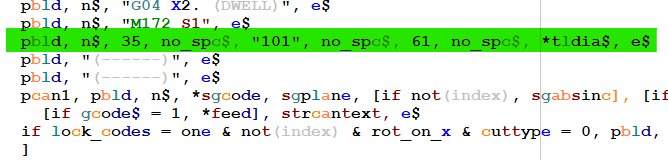
The 2nd picture is the output I got...Yellow Highlight is the output I got.
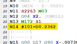
The "D" right before the 0.2362 is the issue. It needs to not be there.
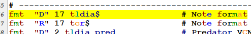
tldia$ looks to be formatted as a note in this post.
Again, I am no post writer, but is there a way to create "something else" that will get the cutter diameter from Mastercam, and be useable for what I need?
As I have been going over this, I am realizing I probably put this in the wrong forum, if so, please let me know and I will tansfer this over to the Post Processor forum...
Thanks in advance for the help and thanks for the help so far...
-
Awesome, thank you...
-
JParis, I'll give that a try.
Thanks to all for the help.
-
Woops...
N1 is just there as a generic line number.
It could always be N1, or just follow the sequence of N numbering that the post does for line numbering.
#101 will always wants to be the exact same, every time it is output. Essentially is could be hard-coded in...
0.125 is there to represent the true defined diameter of the cutter in Mastercam. I just used a generic number to represent it, but, if the defined cutter in Mastercam was 1/4" diameter end mill, then this value would want to be that exact diameter, in decimal output, which would be 0.2500...
I am unsure what you are asking, about where the variables would be stored.
What I am trying to achieve is having the exact diameter, from Mastercam, output in the format above into the NC program, and when the NC program with this line is run at the machine, the machine will hit that line, read the info, and set machine variable #101 to whatever numeric value is there...
Not sure if the clarifies it, but thank you for the help.
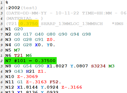
Shown below is output I'd like to see...
Yellow highlighted is the cutter used in the operation
Green highlighted is what I would like to see output from the post..
-
I want to edit my post to output the Programmed Cutter diameter as a Fanuc Variable.
Have searched in the forum, haven't been able to find an answer.
I am no post writer, but have been given to task to figure this out.
Makino Pro 6 control
Mastercam 2022
MPMaster Post.
I'd like to see the output as below:
N1 #101 = 0.1250
Thanks for the help...
-
-
Howdy everyone.
I am looking for help on how to eliminate any sort of G54 / Work Offset output.
The post(s) I am starting with are 2022 versions of MPFAN and MPMASTER, not edited at all, just downloaded.
Any guidance on how to accomplish this would really be appreciated...
Thank you...
-
Awesome... Thank you so much...
I had a feeling you would have an answer...
I'll give this a try...
-
 1
1
-
-
Good morning.
I've been searching the forums, can't seem to find anything on this...
I would like to force a feedrate output, in my NC code, at every operation change, ---even--- if the feedrates from the previous operation and the current operation are the same, in Mastercam...
Is there a way to do this through the post?
Mastercam 2022, using a hacked up old post that was here before I ever got here...(typical, right...?)
Thank you...
-
Howdy everyone...
Trying to get cutter comp to work on a Makino V33, Pro 5 control.
Don't fully understand the whole H1 D2 thing, but I don't really want to (yet).
I just want to get cutter comp to work, so I can adjust the size of a hole, right at the machine.
In Mastercam 2022, I am doing a Contour 2D operation, just cutting a 0.5000" diameter circle, in a piece of material
I am in this case using Tool #3, inside of Mastercam.
In Mastercam, Comp type is set to WEAR, comp direction is Left, the post outputs the G41, and whatever D number it is outputting right now, I have had it set to many things.
I have line on and arc on, in Lead-in / Lead-out
In the NC code, if I set the D number to D1, on this particular Pro 5 machine, I get an error. Don't have a screen shot of the error, bad on me...
If I set the D number to any other number (D2, D3, D17 were all tried), the program will run.
I have 0.0000" in the D Geom field for T3, and 0.0000" in D Wear.
But...
When I put a comp value into the Tool Table, in D Wear, for Tool #3, I get no change in the diameter I am cutting.
I don't get any errors, but it is not changing the diameter that it cuts.
I tried a large value, like -0.1000", in D Wear, and no change...
A little more info...
I am also running a V33i Pro 6 Machine.
On that particular machine, I have found that H1 D2 works.
I program the circle exactly as above.
I have 0.0000" in the D Geom field for T3, and 0.0000" in D Wear for T3.
Program will run, and I will get a 0.5000" diameter circle.
If I go into T3 D Wear, input -0.001", the program will cut the circle -0.001" per side smaller, so the cutter comp I input actually affected the cut.
Yes, I can and have posted and reposted and reposted and reposted, to adjust the hole, and yes, that does work. But, I am having to make adjustments continually, and applying cutter comp right at the machine would sure make things alot easier.
I am machining +0 / -.0002 diameter tolerance dowel pin holes in M2 hardened steel (that stuff that cutters used to be made of, before carbide), and with many many holes to cut, I am having to adjust the ccomp alot. Again, sure would be nice to be able to do that, right at the machine.
Any ideas as to why the ccomp is not taking effect?
Thanks for the help in advance...
-
I have not been able, in 2017, to use keystrokes to turn all levels on / off.
Got real used to using it in earlier versions.
Other than clicking on the icons to turn things on and off, is there some keystroke combination that will do this?
I am using keystroke recording software to execute some laborious tasks, and I used the keystrokes for All on / off quite often.
Thank you.
-
Done some experimenting, seems to be the "first" Solid, in the Levels, in descending order, from Level 1, on down through all the Levels, that Mastercam "sees", is the "Workpiece"
I put a solid, say on level 10, with some "wacky" shape, and if I then turn on Workpiece in Verify, I can see that exact same "wacky" solid, as my Workpiece...
If I then put some other solid, say on level 2, maybe it's not so wacky, but just more "weird" shaped, then when I go to verify, I don't see the "wacky" solid as my Workpiece, I now see the "weird" solid as my Workpiece...
Interesting...
Thanks...
-
Howdy.
So, I have found how to set, in the Verify options, which level Mastercam Verify is to us as my "Fixture" Geometry.
But, somehow, it already knows the geometry that is to be my Workpiece, even though I have never set it explicitly.
How does it know?
Where would this setting be found?
Thank you...
-
Well, if this is a no-no, I am sure that the moderator will take it down, so here goes…
I am in need of someone to do VBScript / NET Hook paid development for me, in Mastercam X9.
I had a guy lined up, but then the boss's boss shot it down due to cost, and I think that burned a bit of a bridge, and that guy won't return my calls anymore.
I don't blame him.
So, I am going to do this on my own.
But I still need a developer.
I have tried to make the time, to learn scripting, but I just do not have the time.
I have a few "have to have it now" kinds of things, and then I have some longer-term things I'd like to have developed.
If anyone is interested, please message me.
If this post gets pulled, oh well…
I had to at least try.
Thank you...
-
-
What do you power users prefer? I've been using standard Verify 98% of the time since Simulation came out simply out of a lack of taking the time to familiarize myself with it. Have been working with Simulation a little more at a time, and find that it loads and runs faster on large toolpaths, and like that Backstep ability. I have found that it lacks the ability to use Stock Model for stock, which I find frustrating, and I havent figured out where stop on collision is yet, or if it checks against fixture collision.
So, it's not just me then???
I have been searching for the ability to load an 'in-process" STL, and Verify against it, in the "new" Verify, and can't find out how to do it.
Am I just missing something?
Not opposed to learning, just have not figured this out yet.
Thanks...
-
1
-
-
Well, new machine, Quaser MF500u in shop.
Fanuc 31i B5 control. Humongous screen. Love it compared to our other "dinky" 31i A5 screens on our Roku machines....
Actually a really nice machine, but no State-side Applications Engineers...
Crazy...
Ran a line of code, to cut a full circle. Cut fine, except that the hole produced is too small, by .008" per side.
Hole is round within .0005", but too small...
No G41 in code, No value in Diameter offset in machine control.
G40 is executed at beginning of program, to cancel any cutter comp...
Checked cutter diameter, over and over. Spot on 1/4" End mill (maybe off by .0005" per side, but not .008" per side, for sure...)
Cutter is a Bull nose, yes, but straight diameter of cutter is doing the cutting, in this case...
Was programmed using 2D Swept, X9. Not neccesarily what I would have used, but so what. Not certain how that might affect things, but???
Hole is modeled in Mastercam as a 0.343" diameter.
2D Swept Operation has -.0005 stock to leave.
0.343" diameter / 2 = .1715" hole radius 0.1715" - 0.125" cutter radius = 0.0465" 0.0465" +.0005" stock t leave = .047"
IJ value should be 0.047"...
CAMplete outputs J value to be -.047"...
Output I am getting from post (CAMplete) gives me (1) line of code, to do a full 360 degree circle.
If I manually break the arc into 4 quadrants, same exact IJ values, hole comes out on size.
Totally confused.
Code below cuts hole using (1) line of code...(Original CAMplete output)
%
O1001 (O1001)
(Generation Date = Tuesday November 10, 2015 Time = 09:21:27 AM)
(Machining Setup = Quaser MF500u - Fanuc 31iMB - No Fixturing)
(NC Format = Quaser - Fanuc 31i - [ G68.2 / G43.4])
(T3 ,Gauge Length=4.219 in,Stickout Length=1.219 in)
(G54 X, Y, and Z Machine Coords: X: 0 in Y: 0 in Z: -13.2951 in)
G00 G17 G40 G80 G90 G94 G98
G49
G49 G53 Z0.0 M05
G69
(Cutting Tool = T3: 1/4 EM WITH .02 RAD - Bullnose 0.25-0.02 in)
T3 M06
G49 G53 Z0.0
M01
(O1000)
S3820 M03
G00 G90 G54 X0.0 Y0.0 A0.0 C0.0
G43 Z3.0000 H3
G01 X2.6181 Y1.4053
Z1.65 F60.0
G03 X2.6181 Y1.4053 I0.0 J-0.047 F30.0
G01 Z5.0 F60.0
G00 G90
G69
G49 G53 Z0.0
M05
M09
T1
M30
%Code below here cuts hole using 4 lines of code: (Hand edit I did)
(Drew up the arc / circle in Mastercam, in the exact position in X / Y, got the coordinates for the quadrants, manually edited the code...)
%
O1099 (O1099)
(Generation Date = Tuesday November 10, 2015 Time = 09:21:27 AM)
(Machining Setup = Quaser MF500u - Fanuc 31iMB - No Fixturing)
(NC Format = Quaser - Fanuc 31i - [ G68.2 / G43.4])
(T3 ,Gauge Length=4.219 in,Stickout Length=1.219 in)
(G54 X, Y, and Z Machine Coords: X: 0 in Y: 0 in Z: -13.2951 in)
G00 G17 G40 G80 G90 G94 G98
G49
G49 G53 Z0.0 M05
G69
(Cutting Tool = T3: 1/4 EM WITH .02 RAD - Bullnose 0.25-0.02 in)
T3 M06
G49 G53 Z0.0
M01
(O1000)
S3820 M03
G00 G90 G54 X0.0 Y0.0 A0.0 C0.0
G43 Z3.0000 H3
G01 X2.6181 Y1.4053
Z1.65 F60.0
G03 X2.5711 Y1.3583 I0.0 J-0.047 F30.0
G03 X2.6181 Y1.3113 I0.047 J0.0 F30.0
G03 X2.6651 Y1.3583 I0.0 J0.047 F30.0
G03 X2.6181 Y1.4053 I-0.047 J0.0 F30.0
G01 Z5.0 F60.0
G00 G90
G69
G49 G53 Z0.0
M05
M09
T1
M30
%Probably some parameter on the machine, but it just blows my mind.
Watched it cut away the material with my own eyes, when I broke it into 4 quadrants...
No other change than that...
Anyone ever experience this?
All our other posts (Mastercam posts) output the arc in 4 quadrants....
Working on getting CAMplete to break circles into quadrants.
Thank you for your help...
-
Bummer...
Thank you...
-
I would like to be able to see hidden edges on Solids as "dashed". Right now I can only find out how to see them "dimmed", just using X9 as it is, out of the box.
Is there a way to show hidden edges as dashed?
Also, in the way back days, MC allowed making hidden edges even another color, as well as being dashed...
Would it be possible to do this in X9 (using C-Hook / NET-Hook / VBScript), showing the hidden edges as dashed, and possibly even making them another color?
Thank you...
-
So, still a stickler for the old days in some ways...
I need (want) to be able to see hidden edges on Solids as "dashed". Right now I can only find out how to see them "dimmed".
Is there a way to show hidden edges as dashed?
Also, in the way back days, MC allowed making hidden edges even another color.
Anyway to do that?
Even using scripting / VB / Chooks?
Thanks...
-
Has anyone else noticed this, that Alt+Right Arrow does not function, but Alt+Left Arrow, Alt+Up Arrow, and Alt+Down Arrow do work...
Can this be fixed?
Thank you...
-
How to Post out Cutter Diameter as a Fanuc Variable...
in Industrial Forum
Posted
JParis, thank you, that did it...