


Niezingerly
-
Posts
150 -
Joined
-
Last visited
Content Type
Profiles
Forums
Downloads
Store
eMastercam Wiki
Blogs
Gallery
Events
Posts posted by Niezingerly
-
-
Beautiful!
Thank you...
-
Good afternoon all.
Is there a way to "import' a custom view, that is defined in a Mastercam file, into another Mastercam file?
Thank you...
-
-
Very good. Thanks, I'll give it a try
-
Sounds good, will give it a try...
Thank you...
-
Hello all.
I am in X6 MU2.
So, been in Mastercam since V9 days, and to this day, still using Flowline for certain things...
I am trying to update my methods to using only the newer style Surface High Speed toolpaths.
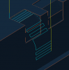
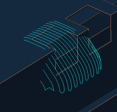
I have attached a picture of an operation that I still use Flowline for.
I would like to find a Surface High Speed toolpath that will give me a similar result.
So far have yet to find something that will give me the result I need.
In the picture, the toolpath is zig-zagging side to side. I need to see it do that, and would need any "new" toolpath to do the same.
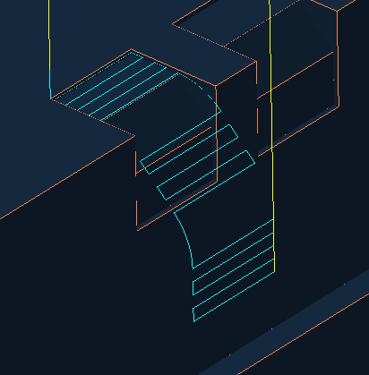
I tried raster, and it gave somewhat of a result, but not fully what I need to see. (See pics below)
The best I so far could get with it was zig-zagging up and down, but for the cut, that is un-acceptable
Any ideas would be appreciated.
Yes, I could continue to use Flowline, but would like to find something newer and better...(and not just for the sake of "newer")
Thanks
Old Flowline toolpath
New Raster Toolpath

-
I run an older iTNC530, on a Mikron HSM 400u machine, and was told about, and experienced once the following...
I was told in 5 axis toolpaths, that for any given point in space, there are (2) solutions, and sometimes the control will jump from one solution to the other, and the part can flip over or swing around wildly.
I had this happen to me once, and luckily it did not crash the machine, but scared the snot out of me...
An example is as follows:
Say you are doing some 5 axis movement, (XYZBC in my case).
You are at a location, say X-1.0, Y+0.0, Z+2.0, B-90, C0.0
Your next move is say to X-1.0, Y+0.0, Z+3.0, B-90, C0.0
From the point you are at, to the point it is to move to, it should move Z positive 1.0, and that is it.
Nothing else should really happen, especially no B or C movement.
But, the machine flips the part around and over from B-90, C0.0 to B+90, C180…
So, it went from X-1.0, Y+0.0, Z+2.0, B-90, C0.0
to X+1.0, Y0.0, Z+3.0, B+90, C180…
Take a look at the numbers above carefully.
The tool was in X negative, and it jumps to X positive.
The B axis was at B negative, and now it is at B positive
The C axis was at C0, and now it is at C180.
It is due to the kinematics, as you said…
Scary stuff…
So, on my iTNC530, what I did to eliminate this possibility, was I locked down (with a parameter), my B axis, so that it can ONLY move from B0 to B-90, and not from B-90 to B+90 (My machine can swing from B-90 to B+90, and it has full 360 degree rotation about the C axis.)
On the newer iTNC530's, there is a setting that will force the same thing, essentially locking the B axis (or any other axis) to movement in a positive only or negative only direction.
I believe it is in the "PLANE" functions. It is called "PLANE SPATIAL"
I have to look this up, but you might contact Heidenhain and ask them about it…
Heidenhain Service support center: 847-490-0351
Depends on the software version of your control…
PM me, and give me your phone number, and I will call you, to try and explain it better than I have here…
-
Thanks Mike...
-
Bob, is the Multiple Block Skip Function a Fanuc function, or is it a Makino Pro 5 function?
We have two pro 5 controls here, and I was wondering about that multiple block skip function...
-
Hello all...
The post I use only outputs an N number at each tool change.
What would I change in the post to get an N number output on every line?
I am running X6 MU2
This is the version information:
[post_VERSION] #DO NOT MOVE OR ALTER THIS LINE# V15.00 P0 E1 W15.00 T1347994825 M15.00 I0 O0
# Post Name : MPFAN
# Product : MILL
# Machine Name : FANUC
# Control Name : 6M
# Description : GENERIC FANUC 6M STYLE POST
Thank you for your time...
-
Thank you...
-
This is the version:
[post_VERSION] #DO NOT MOVE OR ALTER THIS LINE# V15.00 P0 E1 W15.00 T1347994825 M15.00 I0 O0
# Post Name : MPFAN
# Product : MILL
# Machine Name : FANUC
# Control Name : 6M
# Description : GENERIC FANUC 6M STYLE POST
Thank you...
-
Good morning.
The post I use only outputs an N number at each tool change.
What would I change in the post to get an N number output on every line?
Thank you.
-
Sounds good.
Thank you very much for the info...
-
Before I go digging, I wanted to ask here...
Is it possible to have a script edit / overwrite the "Total Tolerance" value, in multiple operations, that have been explicitly selected, with a value that I determine?
These will ALL be surface operations, not 2D Contour operations...
X6 is what I am running...
Thank you.
-
Thank you...
-
Looked it up, looks good.
Gonna give it a try.
Thanks very much.
-
Thanks.
On A Form Filler, does it somehow do it automatically, when it encounters a specific window?
I use a similar thing called X Keys, but it is a physical keyboard I have to hit buttons on.
-
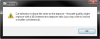
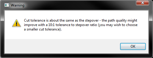
Is there a setting to turn off the warning shown in the pic attached to this posting?
X6, surface Finish Shallow.
Thank you...
-
CAMplete: Yes...
-
 1
1
-
-
I believe CAMplete can outptut APT as well...
-
Thanks very much...
I will try this out.
-
Good morning.
I am no post writer, not even a post hacker, really just a hack...
I am trying to get "M01" to output on the next line, after the tool change, at the first tool change.
All the subsequent tool changes have the M01 on the line right after the tool change, but the first tool change does not have it.
Here is what my current output looks like:
1st Tool change:
T9 M06
S18000 M3
G00 G90 G54 X-1.3938 Y-.3977
Any tool changes after that:
T17 M06
M01 ←←←This is what I want to see output at the 1st tool change...
S6500 M3
G00 G90 G54 X-.5847 Y-.3748
Where would I look in the post, and what would I change to get this to output the way I'd like to see it?
Any help is appreciated.
Thanks
-
He wrote a Macro at the machine, that runs on the machine, to force the H to equal T.
Sidenote: Our Mastercam / post are set to output T, H, and D all the same number. That's not what was going on here...
The reason this is going on is that an operator modified the T call, to call another tool. When he went to modify the H value, he missed the fact that he deleted the value, instead of changing it to match the T number.
This is why the spindle crashed into the part. To the control, the tool had zero length...
So, this was not to be done in Mastercam. Our output is good. It was just one of those one off "...oh, I'll just change the tool call..." moments, and it bit us.
Old file, non-standard tools...
Anyhow, thanks again for all the help.
Just for kicks, here is the macro code for on the machine...
%
(G43 & TOOL HEIGHT COMFIRMATION PROGRAM)
(TEST FOR G43 VALUE)
(OVERWRITE H# WITH T# IF NEED)
(TEST FOR A TOOL HEIGHT VALULE LESS THAN 3.0", EQUAL TO ZERO, OR NULL VALUE)
(LAST UPDATED 10/08/2013)
IF [#4008NE43]GOTO665 (Is G43 Active? )
IF [#4120EQ0]GOTO664 (Is T# Equal To 0)
IF [#4120EQ#0]GOTO664 (Is T# Equal To Null)
IF [#4111EQ#4120]GOTO555 (Is H# Equal To T#)
G49 (CANCEL TOOL LENGTH COMPENSATION)
G43H#4120 (ACTIVATE TOOL LENGTH COMPENSATION)
N555
IF [#5083LT3.0]GOTO666 (Is Tool Height Less Than 3.0)
IF [#5083EQ0]GOTO666 (Is Tool Height Equal To 0.0)
IF [#5083EQ#0]GOTO666 (Is Tool Height Null)
GOTO777 (N777)
N664#3006=175(T# IS NOT EQUAL TO H#)
GOTO777 (GO TO N777)
N665#3000=175(**ERROR** G43 IS NOT ON)
GOTO777 (N777)
N666#3000=176(TOOL HEIGHT LESS THAN 3")
N777
M99
%
X9: Saving Mastercam file while batch/background toolpath generation
in Industrial Forum
Posted
Good morning all.
X9, Windows 7, 64 bit...
I am programming a part, using optirest, and once I click regen for this op, the toolpath gets generated in the "background", and I can continue on doing other programming...
As I do other programming in the same file, I get to a point that I need to save the file, but the optirest toolpath is still generating in the background...
Can I safely Save my Mastercam file, while the toolpath is still generating in the background?
Thank you...