absolute technologies
-
Posts
91 -
Joined
-
Last visited
Content Type
Profiles
Forums
Downloads
Store
eMastercam Wiki
Blogs
Gallery
Events
Everything posted by absolute technologies
-
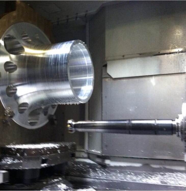
 got overhang? 20hp cuts with 80mm cutter on 27" devibe extension and #50 big plus spindle
-
yeah that's sad, my HP laptop ran 5:40 but I want Motorsports-X's box coming in at 4:09 seconds cheers! Len Dye
-
Samsung Lathe
absolute technologies replied to Rocketmachinist's topic in Machining, Tools, Cutting & Probing
Predator PDM now that's a plague I would avoid full-on.. what a kludge! Unfortunately some Jr engineers bought into this package about the time I returned to work here. I had written my own PDM database that included form based set-up sheets and work instructions but it was too late. The biggest mistake other than buying a POS software was the entire emphasis was getting the documents in PDM with total disregard to the content that was being put in PDM or the value thereof. We totally missed a golden opportunity to re-visit the way we document jobs. After 3 years I wouldn't even call it 1/2 way implemented yet and its' a major cluster-f @ck to maintain. Documentation of the machining operations is one of my pet-peeves in this trade and I'm a firm believer this is best way to address the current skills gap. With solid standard operating procedures and comprehensive work instructions it addresses so many factors in the shop like setup reduction, scrap reduction & training needs. Len Dye -
Samsung Lathe
absolute technologies replied to Rocketmachinist's topic in Machining, Tools, Cutting & Probing
That's the 1st time I've heard anything negative about Ellison. IMHO you can't beat Ellison service here in the SoCal area, no other distributor even comes close except for maybe HFO but that's for Haas machines. Doosan machines offer great value if you're not going with a high-end machine, they've been around quite a while now, have a broad product line and they buy more Fanuc controllers than any builder now too. I'd be leery of relatively new machine tool builders thou. How long has Samsung been making lathes? And they haven't figured where to put the window? Don't they make phones that need the optional fire extinguisher? I can see how Brother got into machine tool building because they bought so many machines it would be better in the long term to develop their own. However their product line is very narrow most likely just machines that they use themselves. Cheers! Len Dye -
FYI There is a Fanuc #5000 parameter that dictates whether the control compensates by moving the tool or shifting the coordinate system. This setting is the reason that you see machine having a tapered move when only 1 axis is programmed, regardless if you programmed compensation perpendicular or not. We have several vintages of Mori Seiki machines here and they were setup different by Mori but I've since corrected them so they don't taper. personally I'd have chit fit if my code had 3 X-axis moves in a row, I would have to totally re-do it.. no doubt! Cheer! Len Dye
- 46 replies
-
- 6
-

-
- CUTTERCOMP
- COMPENSATION
- (and 2 more)
-
Cimco DNC - Backing up Tool Offset Data
absolute technologies replied to Mick's topic in Machining, Tools, Cutting & Probing
Here's part of an old write up I had on MT machine Reading and Writing Offsets to Macro Variables Offsets cannot be read from the Mori Seiki Tool Offset screen in the standard Format. By using a G318 (write to Fanuc variable), or G319 (write to P-code variable) command supplied with the machine, offsets can be read and later re-written to the P-Code Variables. G318 Command Format:(Reading P-Code macro Variables to Fanuc macro variables) G318 A_. Q_. A_. Address of common variable to write data to. #100-#149, #500-#531. Q_. Address of P-Code variable to be read. #11000 to #13399. G319 Command Format:(Writing common variable data to P-Code macro Variables.) G319 A_. Q_. A_. Address of common variable to read data from. #100-#149, #500-#531. Q_. Address of P-Code variable to be written to. #11000 to #13399. Calculating P-Code variable address:Offset data variable addresses (P-Code variables) are obtained in the following way. X-axis Wear #[11000+((H-1) X 10)] H: = Offset Number Z-axis Wear #[11001+((H-1) X 10)] Y-axis Wear #[11002+((H-1) X 10)] Radial Wear #[11003+((H-1) X 10)] X-axis Geometry #[11004+((H-1) X 10)] Z-axis Geometry #[11005+((H-1) X 10)] Y-axis Geometry #[11006+((H-1) X 10)] Radius Geometry #[11007+((H-1) X 10)] Tool Tip Geometry #[11008+((H-1) X 10)] Tool kind Geometry #[11009+((H-1) X 10)] Ex: Geometry Offset data (X-axis) for offset number 5. #[11004 + ((5-1) X 10)] = #[11004 + 40] = #11044 Hope this Helps! Cheers! Len Dye -
are you sure the machine has a HD? other than parameter #3404 bit 2 there are only a few parameters associated with the Data Server that start at parameter #0900. Double check the parameter settings are the same between the different machines Len Dye
-
probably you'll need to change CW & CCW as well as reverse the "I" output too if you're using I & K but you should write a little test program and find out what it needs. Cheers! Len Dye
-
for X- on your Mori change the following line in your post: dia_mult : -2 #Multiplier for output on X axis (Neg. switches sign of X) a value of 1 is for Radius programming, a value of 2 is for diameter programming and a -2 will output X- on diameter Hope this helps! Cheers! Len Dye
-
Make sure your I/O Channel= 5 on your Settings page (same as parameter #0020) Also parameter 3404.2 indicates if the P is a file number (=0) or program number(=1). Typically we have it set to program number and on the HD the filename will be O1234 with no file extension so we would call the program with a M198 P1234 hope this helps! Cheers! Len Dye
-
yes Jaydenn that's very important, thanks! Unfortunately I found this out the hard way where the program had neither the G90 or a G91 on the G10 line so it depends what mode the machine is in when it reads it. The program ran fine for months then one day a big SUPRISE Cheers! Len Dye
-
The way understand the way you want to mange the tool is that it lasts 100 minutes but after 50 minutes of cutting to want it use a wear value of .010. If your machine doesn't have tool life management on the CNC control you can set up a "poor mans" cut timer or parts counter using macro programming. On a Fanuc control you'll need the Fanuc Macro B option though which most builders provide. You'll want to set up a timer for the tool you want to adjust the offset for. You'll use 2 different macro variables, say #500 for time in the cut and #501 for the cumulative total time. You could do all this with just 1 #500 variable but the statements get more complicated so by using 2 #500 & #501 variables is code cleaner and easier for me to explain. For example at the beginning of the tools' 1st cut you'll start the clock with a statement like #3002=0 to set the clock to zero and at the beginning of the 1st cut another statement like #500=0 to set the current time in cut back to zero. At the end of the cut you will stop the clock with a statement like #500= #3002 which will save the time from the internal clock to variable #500. NOTE: if you want to time multiple cuts where the timer is turned on and off while that tool is being used you have to reset the clock back to zero with #3002=0 again then to stop the clock after cutting and add that time to the other cuts you want to have a statement like #500= #500+#3002. Now at the end of the tool you will want to add that time to the cumulative time with a statement like #501=#500+#501 Now #501 has the total time for that tool so now, just as you suggest in your example, at the beginning of the tool change it would look like this M6 T10 IF[#501 LT 50.] GOTO1 G90 G10 L11 P1 R0.01 N1 M3 S5000 G0 G54 G90 X0 Y0 G43 H1 Z1. M8 #3002=0 #500=0 cut... cut... #500=#3002 #501=#500+#501 G28 G91 Z0 M1 So with this example each time the tool is called up with more than 50 minutes on it the tool will use the adjusted offset from the G10 line of code. When you replace the tool with a new one you would need to set your #501 cumulative time back to zero with a MDI statement like #501=0 or go to the Macro page and set it to zero there. Also you will need to manually set your Wear offset back to zero. Also note that you could set up an alarm to alert the operator when the tool gets to 100 minutes with a statement like IF[#501 GT 100.] THEN #3000=1(TOOL LIFE EXPIRED) and the machine will alarm out or if you don't want an alarm but just want to warn the operator you can send it to the message screen with no alarm with a different #3000 but I can't remember which number it is off hand but it is possible not to alarm the machine out and even possibly call up a spare tool just like Tool Life Management as well. The Fanuc programming manual has a time counter example in the Macro section for 5 tools however it starts/stops the clock with a M3/M5 M-code macro that uses #4120 which is last T command, not necessarily the T that is in the spindle, so be careful. I wouldn't recommend using it though. Which a little effort you can learn macro programming with a challenge like this from the Fanuc book but the language is questionable and it doesn't go into much detail and doesn't explain things very well. A better book would be CNC Custom Macros from Peter Smid Hope this helps! Cheers! Len Dye
-
Open Pocket, why isnt this easier?
absolute technologies replied to slougee's topic in Industrial Forum
wow I guess I totally missed getting my point across then.. have fun with your Future Based Machining thou... Len Dye -
Open Pocket, why isnt this easier?
absolute technologies replied to slougee's topic in Industrial Forum
I guess I'm a nobody, I prefer to draw my own geometry to dictate the toolpath the way it needs to be not the way MasterCam decides it wants to create it, it's called control, but then again I'm old school. For me it's not about how fast I can create code but rather getting the technique proper and not wasting time at the machine. If I spend a little extra time in the CAM system it doesn't cost the company hardly anything in comparison to wasting time at the machine with some program that took only 30 minutes to create. But then again I don't work for a mom & pop where the owner is looking over my shoulder constantly so I understand many guys are programming parts they'll never see again where it's more important to just crank it out. I do know though there are a lot of programmers out there that are either lazy of just don't know cutting strategy and have to take what the CAM system gives them. We had a couple of parts that we farmed out to an experienced programmer that used all these new school paths. Out of the box it was 16 hours cycle time and after weeks of trying to get it to run we finally got to do a little optimization and got it like 9 hours. After reprogramming with proven strategies it was under 3 hours. With our current orders it was close to 1,000 hours savings for the machining, for each part! Other than just a bad cutting strategy in general the biggest factor in the savings was a 6 meg file vs 300K and the fact that the large file cut air most of the time repositioning itself for the next cut. I found it interesting that the large file only had only a couple of minutes of rapid time where the more efficient program had like 10 minutes of rapids. A 300k file will execute much faster than 6 meg file.. IMHO, other than Mill/Turn and doing some edge breaks, Esprit blows donkeys in comparison. Cheers! Len Dye -
We read the work offsets in with at the beginning of the CNC program using G10. Every job has G54.1 P1 for B0, P2= B90, P3= B180 & P4= B270 then P5 etc for odd angles, it's always the same . for every job and less confusion because every job has the same work offset/B-axis table position scheme, furthermore pretty much fail safe reading the work offsets in with each job. In this case where they're doing tombstones work on different faces, the operators would only need to edit the G53 B work offset at the beginning of the program because one time the fixture may be B90 then next time its' at B270 or whatever Cheers! Len
- 23 replies
-
- 2
-
-
- work offsets
- g54
- (and 2 more)
-
Best Finishing Toolpath for Cavity
absolute technologies replied to randommachinist's topic in Industrial Forum
Your part looks to be pretty much straight arcs along the YZ where the finish surfacing lends itself to a flow-line toolpath that you can dictate the direction. Anytime I can get it to post arcs instead of point to point I'm going that direction. The servo motors will get up speed with the longer G2/G3 moves much faster than a bunch of point to point moves, especially with no look-ahead. In general I choose the direction that will give you the longest motion to get the maximum feedrate out of the servos and this may require breaking the surfaces up into sections to optimize this strategy. Cheers! Len Dye -
"Error Reading From Surface Machining Temporary File"
absolute technologies replied to Leehound's topic in Industrial Forum
are your working with surfaces or solids? -
M19 question for Doosan Mynx 7500
absolute technologies replied to JeremyV's topic in Machining, Tools, Cutting & Probing
On Mori machines there is a keep relay that allows M-codes to be performed during movement or after the movement so I have a M19 on the G28 line so that by the time Z-axis gets home the spindle is oriented and ready for a tool change. There is no need for a M5 as the M19 stops the spindle then orients all in one motion so it's probably faster not to have an M5. This saves about a second per tool change you might want to check to see if Doosan has something similar. I've never heard of M19 causing wear and tear on a machine. At M19 essentially there is current going to the spindle servo motor to hold the spindle position and it takes very little power to hold that position. Cheers! Len Dye -
The functions that use #19700 parameters are G43.4 TCP, G68.2 TWP and G54.4 Work Piece Setting Error Compensation. I've often wanted to do what you have done with the probing of a sphere, however my thought would be to set the pivot points with mechanical means (dial indicators) then run the probe routine to verify the probe results coincide with the mechanical check such that the operator can run the probe routine anytime for verification. The reason I say set the pivot points with dial indicators it can be way more accurate than a probe with less uncertainty. Then from there do your circle, diamond square test cut or better yet, machine a 5-sided block with various features using TCP & TWP that isolates the pivot points better than the Circle Diamond Square test and that can be inspected using surface plate, height gage and dial indicators with extreme precision, make your final adjustments to #19700's and then verify the test cube on the CMM as a reference. This way you have a solid static mechanical check that is backed up by probing and the 5-sided test piece will give you a dynamic look at the volumetric accuracy. Back in mid 80's I was involved with the installation & commissioning and was the operator on the 1st 5-axis machine in the US. We didn't have probes back then. One of the first jobs was a drill jig with true position of .001 on compound angled holes. The 1st part came out about .020. We went back to the old method of setting the spindle angle, pick up a tooling ball and bored the hole on location. After that job we re-vamped the machine and it got about 10 times more accurate. Here we are in 2016 and we still need to be about 10 times more accurate than where we are today IMO. I used to work for the Mori dealer and was involved with their 5-axis machines when they 1st came out. Mori had no clue on how to get the pivot points down to a tenth or less. Up until a just a couple years ago they still had no clue. At the same time we also sold high end Euro machines like Jobs and Fidia. If you have a chance, check out how Fidia sets their pivot points. Its' amazing there is no industry standard for this and customers are left to the expertise of the machine builder. Cheers! Len Dye
-
ULTIMATE MACHINE SHOP TOOL CART IDEAS
absolute technologies replied to WOODS7's topic in Industrial Forum
We don't have any Haas machines so no need for the ball peen hammers here The surface plates are up on 3-point risers so there's a gap between the cabinet top and the surface plate and the cabinet has about 6" more depth than the surface plate so there's a decent size ledge there to put the wrench and dead-blow hammer while working. Typically the only tools on top of the surface plate are the measuring tools and they are on top of shop towels. BTW, also no personal tool boxes here either! Cheers! Len Dye -
It's been my experience that many service technicians when doing the ball bar test end up over compensating the back-lash setting. It seems they tighten up on the electronic backlash setting that makes the ball-bar plot look better however physically there is no back-lash and the machine is over compensating. A good test to make sure back-lash isn't too tight or too loose is to mount a .0001 indicator in the machine and touch off somewhere. With the machine in .0001 handle mode, move the machine in the + direction one click at-a-time, watching the dial indicator then come back negative direction 1 click. You should have at least 1 no more than 2 clicks in the opposite direction before the dial indicator needle starts to move. If you come back 1 click and the machine only moves a half a tenth then you can't get much better than that but if you come back 1 click and the machine moves more than .0001 or does a little dance then its' likely your back-lash is probably too tight. Physically the machine has to have some back-lash, just not too much and certainly you don't want it over compensating. Good Luck! Len Dye
-
Fanuc OI-TD run program issue
absolute technologies replied to mirek1017's topic in Industrial Forum
there is a Fanuc parameters to lock 8000 & 9000 programs from editing or erasing them but you can still run them (NE8 3202.0 & NE9 3202.4). Other than that there is no parameters that I know of that would prevent it from running other than the standard Machine Lock or Edit Lock functions. Good Luck! Len Dye -
ULTIMATE MACHINE SHOP TOOL CART IDEAS
absolute technologies replied to WOODS7's topic in Industrial Forum
We have mobile Lista cabinets at each machine with a surface plate on top and the computer workstation attached to access working files. Each tool box has all the necessary hand tools in drawers that are shadow boxed as well as some basic measuring tools and full set of gage pins at each machine. The cutting tools are pre-kitted in the tool crib so there really isn't a need to store tool holders at the machine so the carts with holes in them for the tool holders are only used to transport the tools back & forth to the tool crib. The only thing missing maybe is a set of jo-blocks and the keg-a-rator We have a couple of mills that are dedicated for a family of parts where the cutting tools are managed by the operators at the machine, not the tool crib. They have an area behind the machine to store and work on their tools and they load the tools in the magazine right there so no tool cart there to transport the tools. Cheers! Len Dye
-
deflection is a direct function of length to diameter ratio of how far the end mill sticks out of the holder and hardness of the material, with climb cut the deflection will push away from the side and with conventional cut the deflection will suck it into the surface, the trick is to not let the conventional pass cut too much material so that it doesn't suck in but rather just dust the surface and take the taper out from the climb cut. The sharper the end mill the better as well, sometimes when replacing the end mills I only replace the conventional cut end mill and use the used end mill for the climb cut tool or the rougher to get a lil more economics out of it. Obviously with carbide being 6X more stiff than HSS you want to use carbide. glad it worked out for you! Cheers! Len Dye
-
yeah maybe rough to +.001-.002 stock per side and maybe only a .0001-.0002 per side for the conventional cut, but .0005 isn't going to kill it. I usually program the climb and conventional cut right to finish net and just use the CDC so the last endmill just dust the surface. We recently did a .040 slot +/-.001 on size and location that was 8xD with Harvey end mills on heat treated S.S. and worked like a champ. Anytime I can use a drill to remove as much of the slot as I can I will do that as well. Cheers! Len Dye