Kendo
-
Posts
65 -
Joined
-
Last visited
Content Type
Profiles
Forums
Downloads
Store
eMastercam Wiki
Blogs
Gallery
Events
Everything posted by Kendo
-
Maybe it should be max pitch instead of a hard coded pitch value I've never done helix bore and not wanted 360 arcs and nice simple code output from the quadrant I bet some of you guys have done threads though that have the starts called out?
-
Thanks for helping JP I'm my own worst enemy, it was the linearize helix checkbox I still think they should fix the helix bore bug, when you set the start angle and the depth doesn't divide evenly by the pitch, Mastercam seems to translate the start angle to an end angle, the the start just ends up where the math puts it.
-
crap.... it was the linearize helix checkbox sorry guys I haven't written a new program in a while
-
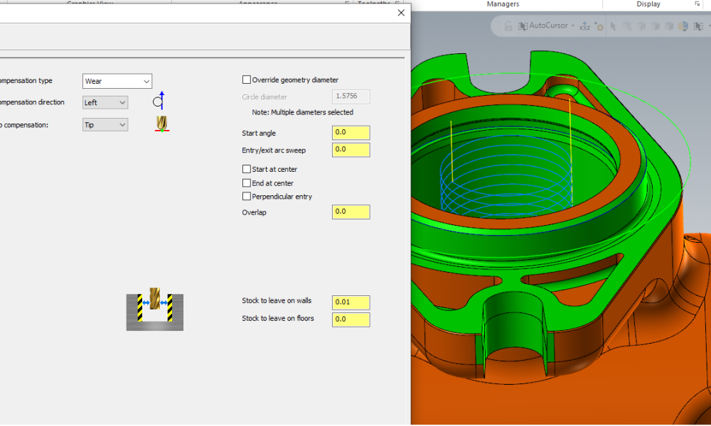
Ok I did It's better, but now the arcs are about 260 degrees Geometry is a single entity, full circle
-
Because I'm fighting 360 arc output issue once again, even though I set the arc parameters, I still get tiny segments Helix bore does 360 arcs, contour ramp won't Would post a picture, but for some reason I can't because file size too large, even if I try to re-post the same picture I posted above
-
8 years later, same thing
-
I figured I could use boolean to subtract the finished part from the raw casting model, but that's against the "rules" Results in multiple disjointed bodies as the casting is being machined on several faces What do the pros do? I was looking for an easy way to make sure I don't miss anything... doing a bunch of timestudies this week
-
Can't find it... (MC 2024)
-
Thanks Simon, but that had no effect After searching for and installing the driver, then re-starting windows and letting it install other updates, The same behavior in the video above is still present Our IT guy is going to chip in with me to help answer Millman's questions shortly
-
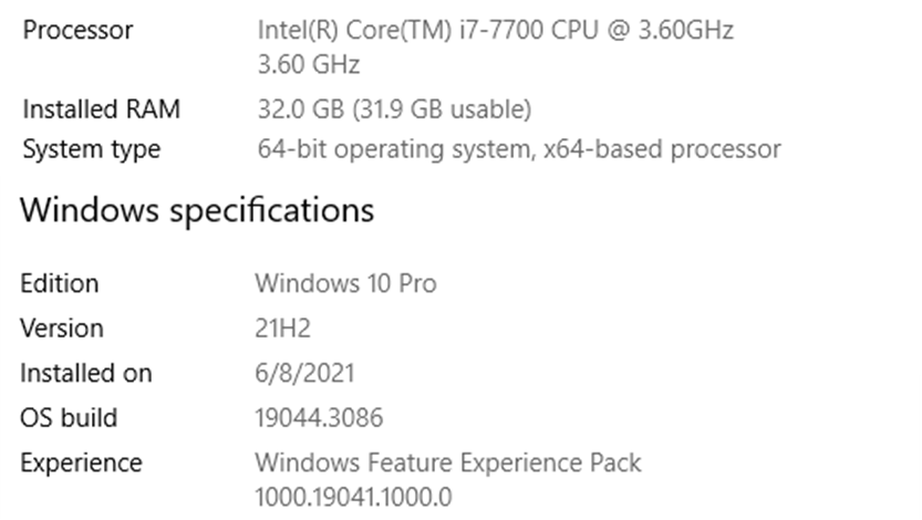
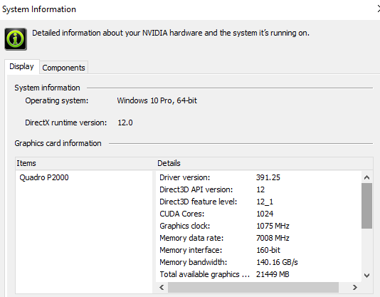
It sounds like if I answer those four questions there's forty more in the chamber System info below, but what NVIDIA settings... all of them? Is there a tutorial or training course for this, or should I go for a computer science degree?
-
Thanks millman, but that had no effect
-
I'm using 2023 and the simulation basically ignores all the view settings I've tried The views don't sync between mastercam and simulation The workpiece moves all over the place even though I set focus to workpiece and the view flips 180 degrees every time a new operation begins WTH.mp4
-
Thanks guys that's the right direction! I was stuck thinking of everything under the 3D tab as "3D surfacing", not for prismatic parts like this
-
I got an open pocket to work with 2D dynamic mill and using containment / avoidance areas Now need to figure out the rest milling / machining from the stock Seems like programming to the 3D model instead of 2D geo, Mcam would be able to figure out the stock without containment / avoidance Maybe I'll figure that out next... I'll poke at it some more
-
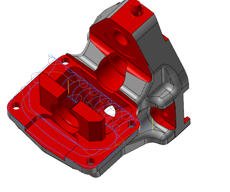
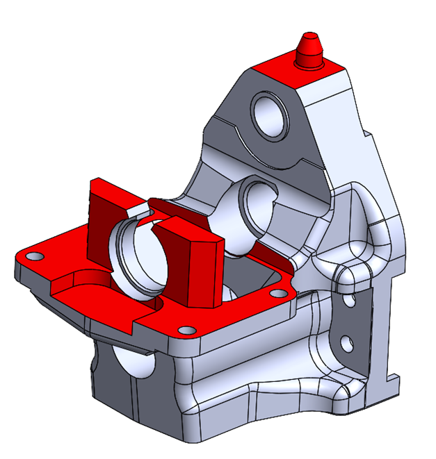
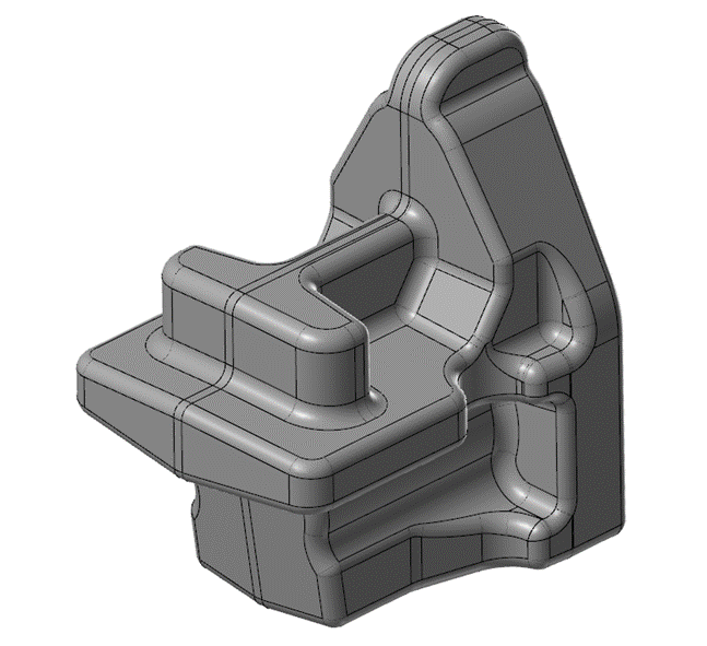
Getting frustrated trying to figure out the toolpath for this 2D cut... The face with 4 holes thru is my focus To me it looks like a pocket with 3 open sides and an island, should be easy right But I'd like to calculate the cut from stock model which is mostly air 17840-1_New_Machined.mcam
-
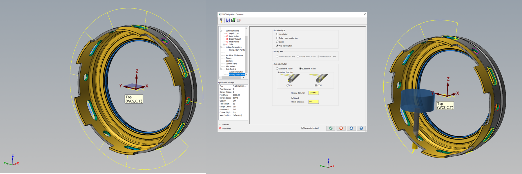
Wow, thanks Rekd Also, Aaron... your settings helped as well with the backplot and mach sim The holes will be interpolated with same endmill I was having a hard time getting contour ramp with 3D geometry, so I went 2D The part is tapered so picking the geometry off the model was weird... but I wish it was that easy I got it to "work" so far... just need to get the A-axis position and "unrolling" figured out.

-
The model isn't correct, see above I need the cycle to proceed in this manner: slot-hole-slot-hole... (I think) If I transform-rotate a single tool path I have to make one for the slots and one for the holes Then it'll be: slot-slot-slot *then* hole-hole-hole (two trips around)
-
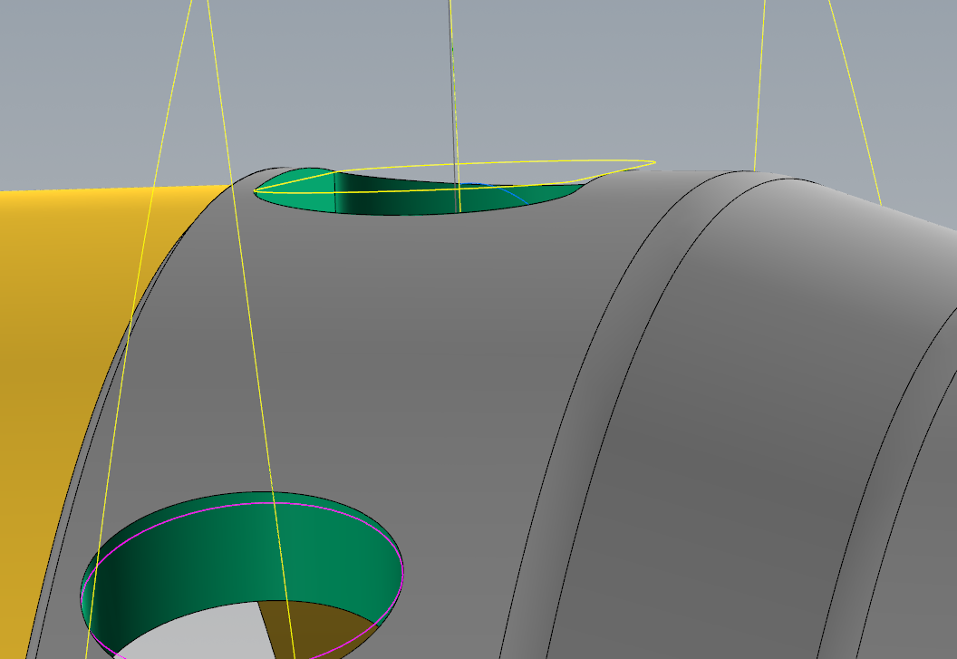
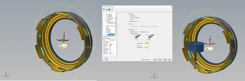
Thanks guys, I'm processing this info, Meanwhile heres the file and the robodrill mach sim I created the slot and hole geometry instead of picking from the model, because the planar geometry gives me the ability to contour ramp The 3D geometry on the model wouldn't let me ramp. Also, this model isn't correct. The slots are all being cut radially (with rotary axis) like the slot at the top (see below) ROBO_DDR.zip ROTARY SLOT.mcam

-
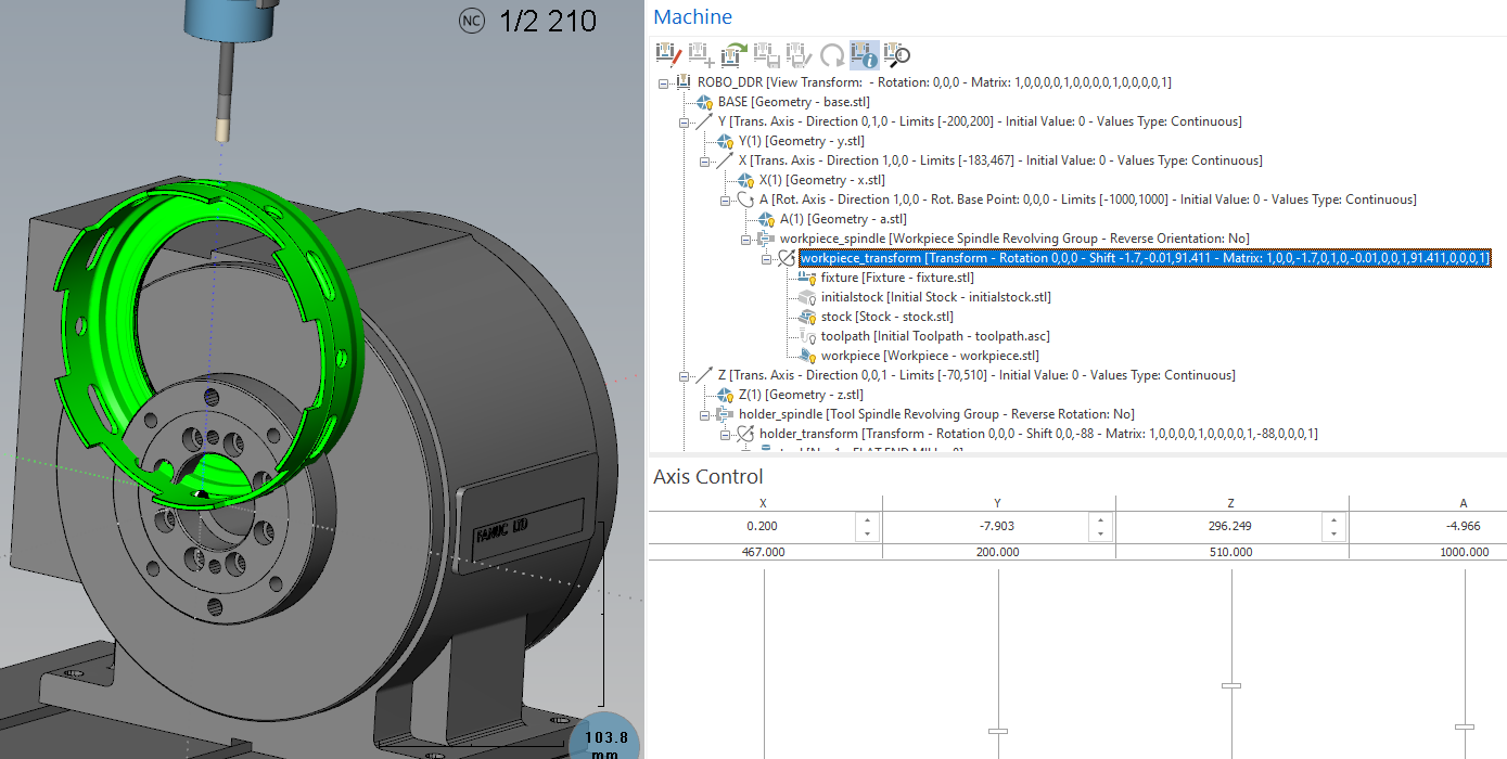
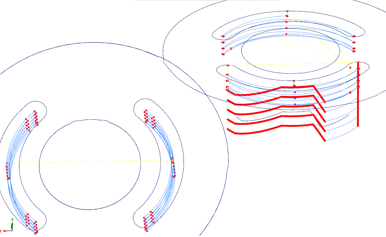
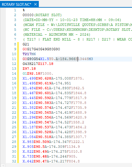
Theres a lot going on in this file I could use some help with... I even built my own Robodrill for sim and it worked fine til I got into this... 1st off, backplotting is giving me this weird result even though mach sim looks right (normal?) I chained the top slot and then proceeded CCW to all the other slots/holes... but the path is going around 2/3 of the way, then indexing back to finish the last 3. The A axis needs to index continuously around the part The code output below, I don't know why the first slot isn't at A0. The top slot in the model is what I chained first, but the code is indexing to A-184 degrees Finally, at bottom, the mach sim is doing some weird shift when the model is visible. I set the model as stock in the properties. If I simply hide the level the model is on, then mach sim puts it on center like it should, with no shift...??

-
Thanks again JP That cleaned it up a lot I'll play around with the chook in the future I also understand that tolerance setting now thanks to you That was a good catch!
-
That's so weird, this was addressed in my other thread a while back That weird slot is so easy to code longhand with the cad points And its 5 lines of G2/G3, but Mcam craps its pants
-
Thnkas JP, that worked on the two sets of arc slots Any idea about the weird slot? Can't get it to quit making segments
-
File attached, The weird arc slot is in there, which I've talked about on this forum before Funny thing, MC outputs 3D arcs for some of this ramp slot And G1 segments on the weird slot WHY can't they all be G2/G3 !!?? The only G1 moves should be Z! Fixed segment even broke up the Z, but not the flat arc at the bottom... pretty weird DEEP SLOT.mcam

-
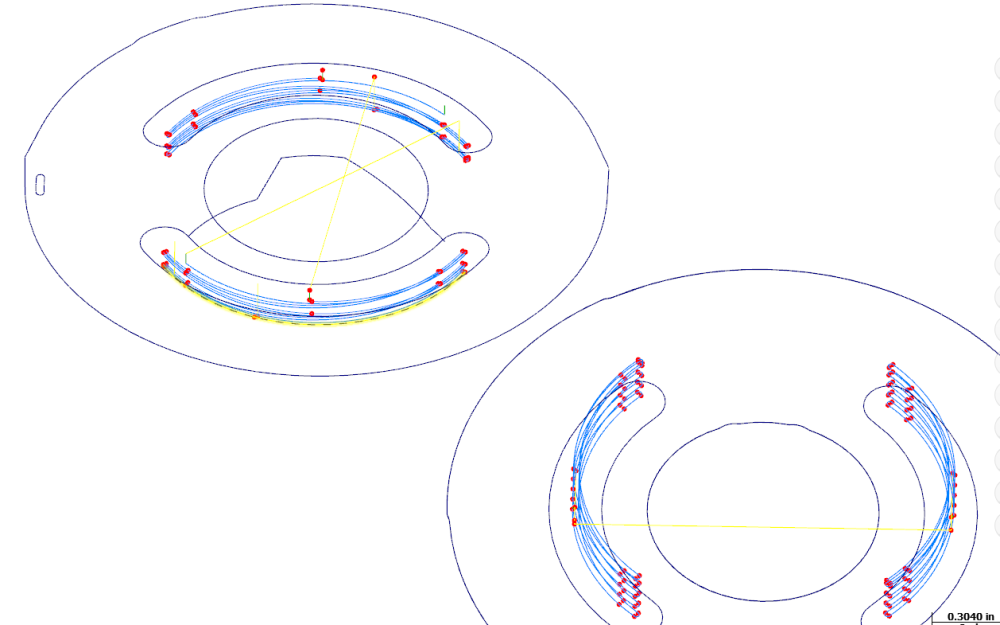
These two ramp contours won't output arc moves! The little 180s at the end of each zig-zag keep coming out as G1 segments Even though I set the arc filters the same: The one on the right is all G2/G3 (what I want) But the one on the left gives me a bunch of G1 The endpoints display doesn't show me this will happen I saved the toolpath as geometry On the right: some are arcs, some are nurbs - but they all come out as G2/G3 On the left: same, arcs and nurbs... but all the nurbs come out as G1 segments! FYI: These arcs are broken into 3 segments so I can slow down the feed at the ends where engagement is max But I'd like the tiny 180s to be true arcs, and flatten them if possible tried twice to post the image...
-
Humerus Thanks, I see that could work I know this 3+2 is relatively new, the video I watched said if you don't like the results from automatic 3+2 just go back to using opti-rough and a bunch of stock models