-
Posts
36 -
Joined
-
Last visited


[email protected]'s Achievements
")


-

Threadmill Comp not working 2019
[email protected] replied to [email protected]'s topic in Industrial Forum
So If I turn perpendicular entry off My cutter comp does kick in. Which is great except for some reason Mazak can't comp on a helical move this is why I have to use the perpendicular entry. so yes it works but not for what I need it for. I am guessing this is software based not post based as it has been working for me for many years up to this point. -
Threadmill Comp not working 2019
[email protected] replied to [email protected]'s topic in Industrial Forum
yes perpendicular entry is on.( Mazak need this on to cutter comp) and I tried .01" increments on the Entry/exit clearance from .01 to .100. no success. In my 2018 version I do get cutter comp but if you look at the 2019 version there is no G41. -
Is this a 2019 Glitch? I am making a 1/8 NPT hole with my thread mill done this 1000 times. put it into 2019 and its not posting with cutter comp anymore. I can work around it by changing my hole size on my computer but its a bit annoying. 2018 (T4 - 1/8" NPT THREAD MILL - DIA .31") T4 M06 G00 G17 G90 G54 X0. Y0. (TOP MAPPED APPROACH POINT) M46 M43 (B-AXIS UNLOCK, C-AXIS UNLOCK) G68.2 X0. Y0. Z0. I90. J90. K0. G53.1 P1 M47 M44 (B-AXIS LOCK, C-AXIS LOCK) S3000 M03 X0. Y0. G43 H#3020 Z.1 G01 Z-.4 F15. G03 G41 D4 X.0345 Z-.3907 I.0173 J0. F10. X.0345 Y0. Z-.3537 I-.0345 J0. G40 X0. Z-.3444 I-.0172 J0. G01 Z-.4 F15. 2019 (T4 - 1/8" NPT THREAD MILL - DIA .31") T4 M06 T2 M08 G00 G17 G90 G54 X-2.75 Y0. (TOP MAPPED APPROACH POINT) M46 M43 (B-AXIS UNLOCK, C-AXIS UNLOCK) G68.2 X0. Y0. Z0. I90. J90. K270. G53.1 P1 M47 M44 (B-AXIS LOCK, C-AXIS LOCK) S3000 M03 X-2.75 Y0. G43 H#3020 Z.1 G01 Z-.4 F25. G03 X-2.715 Z-.3907 I.0175 J0. F10. X-2.785 Z-.3722 I-.035 J0. X-2.715 Z-.3537 I.035 J0. X-2.75 Z-.3444 I-.0175 J0.
-
Drill selection Enteties gone in 2019
[email protected] replied to [email protected]'s topic in Industrial Forum
by switching that auto cursor setting that will change globally? so when doing drawings and whatnot you would have to go back in and turn it all on? If so I believe that should be addressed in an update soon. Like you said if it would preset the auto cursor only when doing hole selection that would be great. Glad to help Roger. -
Drill selection Enteties gone in 2019
[email protected] replied to [email protected]'s topic in Industrial Forum
Just opened up 2018 makes a circle select drill. when you select Entities you cant select quadrants or midpoints of the circle. but if you click on the Arrow at the top you can. In 2019 its Default seems to be on the Arrow with no option to change to select entities. so again draw a circle do a drill tool path and you can accidentally select the quadrants or a midpoint of your circle. just more room for error in my opinion. -
Just started with 2019 and noticed the entities selection gone in the drill selection tab. I can manage a work around( using the C button to select center of circles) but when working with wire frame its a lot safer as you cant accidentally pick a quadrant of a hole. Is this feature actually gone?
-
I am machining a delrin part in my CNC mill. we have already turned this part on the lathe and it had a large undercut on the part . I have to cut out almost 1/2 of the sidewall out in a specific shape but it is a thin wall piece and because of the undercut i cant put a plug in it so i end up with chatter issues. For a better description imagine machining a 2 liter pop bottle between centers in a mill making a square pocket for 180 degrees. Does anyone know of a medium I could pour in cut out my shape. then dissolve with either mild heat, thinners/alcohol or water? Thank you in advance for the help
-
Multi axis Morph smoothing corners
[email protected] replied to [email protected]'s topic in Industrial Forum
I changed a few things here is the before after. Under cut pattern/ surface quality i turned on maximum distance and changed it to .01" then under advanced options for surface quality i changed the chaining tolerance to .05 instead of .1" thank you husker for the suggestion I will give it a shot see how it looks on my next go around.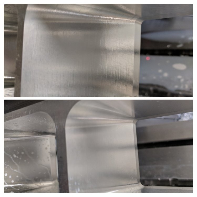
-
Multi axis Morph smoothing corners
[email protected] replied to [email protected]'s topic in Industrial Forum
here is the file I had to get rid of everything except one tool-path to get the file size down. I changed a few things that seems to be working right now but will be an hour or so before I can see 100% if it worked. I do a lot of these so I am always open to input. sample.mcam -
I am making a port 3" deep pretty much its a 2 x 3 rectangle with 3/4" rads going down to a 2.25" square with .2" rads. I have this mounted between centers in a 4th axis. I am using a morph toolpath to machine the finish pas on these ports but for some reason I'm getting lines in my corners and sometimes across my flats. almost like the toolpath doesn't line up while it goes around. I am going with a .1" step-over so it should be fairly smooth. Any suggestions other than a bunch of polishing?
-
Wondering if in 2018 you can do a floor and wall finish at the same time using 1 single contour. I do a lot of plastic work generally jobbing shop stuff. I hate having to take 1 pass to finish the floor then 1 pass to finish the wall unless I leave .01" on the floor and wall then copy the contour down and get rid of the .01" stock. I saw they made some changes to the finishing passes in 2018 but is this available?
-
Mcam 2017 work offset bug or just a change?
[email protected] replied to [email protected]'s topic in Industrial Forum
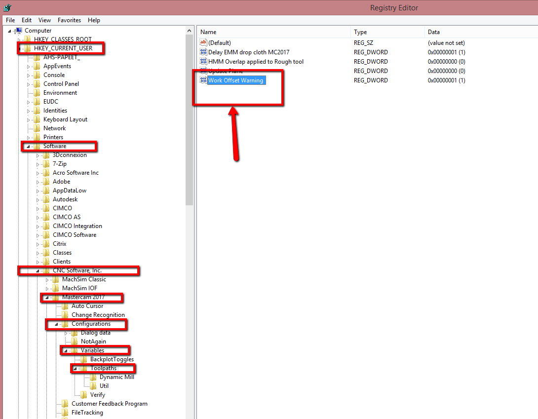
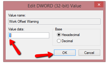
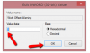
I found a fix to this thanks to my good friends at Inhouse solutions. hope this helps just go into your Regedit.exe and follow these pics there is a pop up that wont pop up unless you do this.
-
Mcam 2017 work offset bug or just a change?
[email protected] replied to [email protected]'s topic in Industrial Forum
I believe that will be my new habit if this is not a bug (although I should just probably do it that way anyways ), but with this program I initially had it all to run off g54 , the 55-58 were an afterthought. -
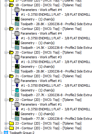
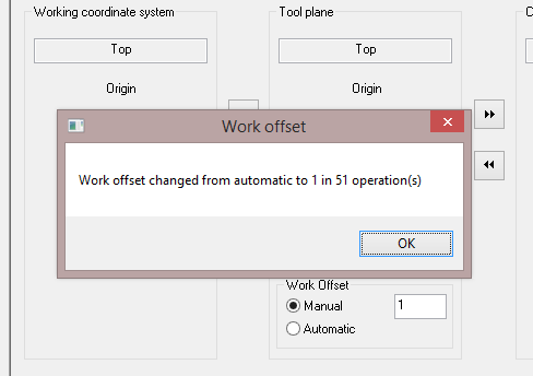
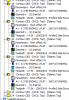
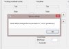
Not sure if this is a bug or just the way they are going to do things from here on out. Here is a small warning to anyone else that may do things the way I do it sometimes Work offset numbering under the same plane info (top,top,top) for instance. I have a fixture holds 2 parts 8 ft long 3" I have to hold a +/- tolerance of .005" I wrote the program all off one fixture offset (51 operations) I found with temperature and machine conditions holding this tolerance to be very difficult and over 8 ft thermal expansion was quite an issue. So in X8 or 9 cant remember which I changed the part to have 5 different offset G54-G58 and G59 for op2 To do this I just changed the work offset under the Planes tab in my toolpath parameters. I have been doing this since mastercam V9 if I remember correctly. No issues. (look at image work offset numbering to see my setup) yesterday had to make a modification to my program took me about an hour generally just copy past rechain geometry all went well. Last op was a new feature I had no previous toolpath for so i wrote the toolpath changed my work offset and I get a the pop up showed in the other pic (work offset change) There was no warning saying it was going to happen would you like to proceed nothing just one saying "hey we changed your whole program!" so being to far in to go back I had to recreate all my planes as a copy of top then label them as G54-59 then replace the planes in all of my toolpaths. One other strange part about this is I can modify the existing workoffsets no problem from the planes tab under the toolpath parameters. Only when adding a new toolpath and changing the offset there will it change the whole works. So I was luck this was only 51 toolpaths I know some of my programs are much more and I know some other people out there have even more complex programs than I. Hope this helps someone out there before they have to do the same thing I did.
-
opening a solidworks file in mastercam 2017
[email protected] replied to [email protected]'s topic in Industrial Forum
Agreed.