MotorCityMinion
-
Posts
1,259 -
Joined
-
Last visited
Content Type
Profiles
Forums
Downloads
Store
eMastercam Wiki
Blogs
Gallery
Events
Everything posted by MotorCityMinion
-
The blend tool path will compress the actual tool path to cram an equal number of passes in between the blend chains, not necessarily using a even step over. If the surface boundaries change, your blend chains should follow suit. Variations in the surface will have an effect. The drastic changes in the tool path pictured is odd. Surface normal perhaps?
-
Wuts rong witdh hiz riteen scilz?
-
My favorite site for SW: http://cadjunkie.com/welcome
-

Whats wrong with solid extrude in X8?
MotorCityMinion replied to bogusmill's topic in Industrial Forum
Try reversing the direction arrow? -
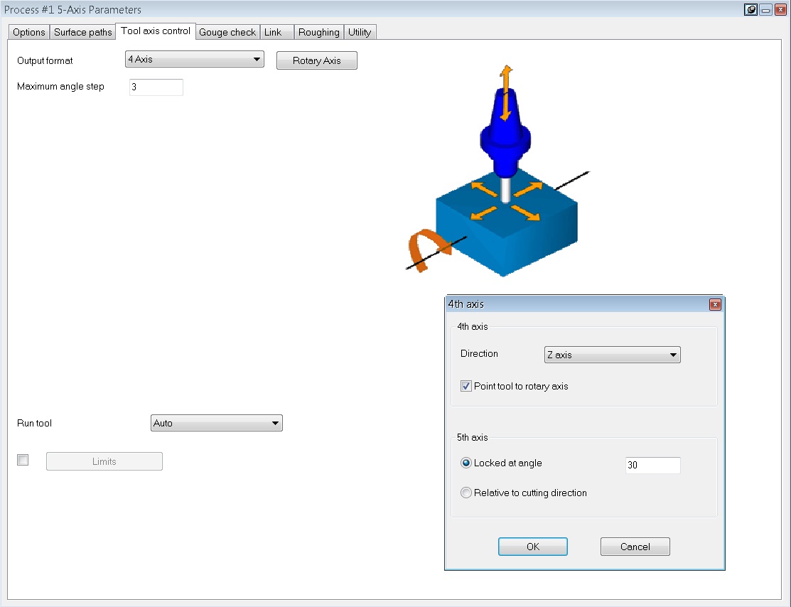
Did you know Mastercam has "hidden" 5-axis toolpaths?
MotorCityMinion replied to Colin Gilchrist's topic in Industrial Forum
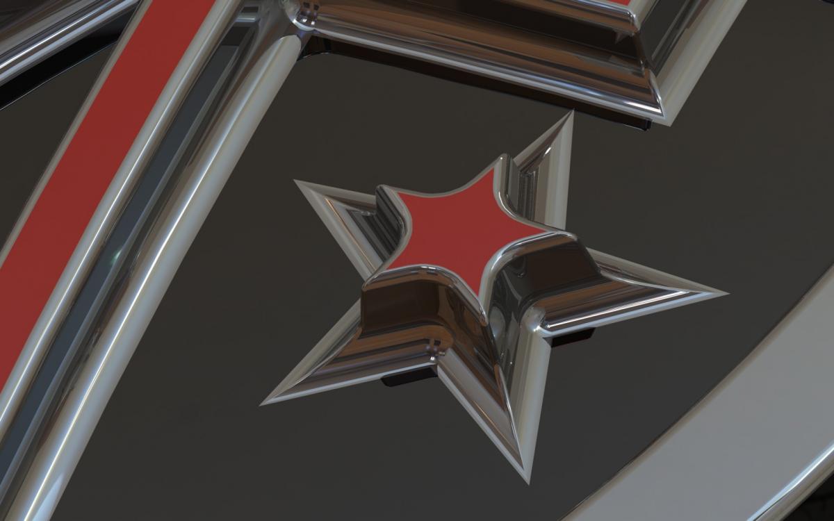
I found some good examples. The part is a Spline punch. The PROJECTION STYLE AROUND pic has the tool path rolling around the exterior in a pure spiral fashion. Smooth as silk and great for roughing and finishing. Watching this run on a 5 axis Mikron is pretty cool. The PROJECTION STYLE ALONG is how I finish the part. Very similar to SF Parallel or Raster except it doesn't fall off the edge as quickly as the tool stays normal to the CL of rotary, rolling the 4th axis as it moves around the part. Both styles are options within the Projection tool path. Best option yet is tipping the 5th axis 10. degrees so the tip of the ball isn't doing the cutting. I wish I had discovered these tool paths while I was still working with MC. ModuleWorks is awesome.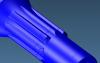

-
Did you know Mastercam has "hidden" 5-axis toolpaths?
MotorCityMinion replied to Colin Gilchrist's topic in Industrial Forum
Hey Newb. I'm still kickin. I still read the forum frequently. More often than not, just for chuckles. Although I'm using a different Cam package at work, the ModuleWorks tool paths are almost Identical to those used in MC so I can still participate here. And like G said above, it;s difficult to get good clean arcs. These tool paths like a tight tolerance as well. Set them tool loose, and they get jagged quickly. Constant Z , Projection, and morph between surfaces are my favorite tool paths now. I'll upload some screen shots if I can remember how. Have you heard from Ninja? -
Did you know Mastercam has "hidden" 5-axis toolpaths?
MotorCityMinion replied to Colin Gilchrist's topic in Industrial Forum
I've been using the Moduleworks / Triangular mesh tool paths in another Cam package for some time now. They do a very good job. The constant Z tool path, which is basically a Waterline, contour style machining, is far superior to what I've used in other packages. It will spiral with no linking moves. More lead in and out options and a host of other goodies as well. The real bonus is that once you learn these in 3 axis, the leap to 5 axis isn't as bad. -
I use this exact feature in another CAM package on approximately 30% of the models I do surfacing work on. It's almost priceless.
-
Need help with multi axis OD surfacing
MotorCityMinion replied to Chipmakr's topic in Industrial Forum
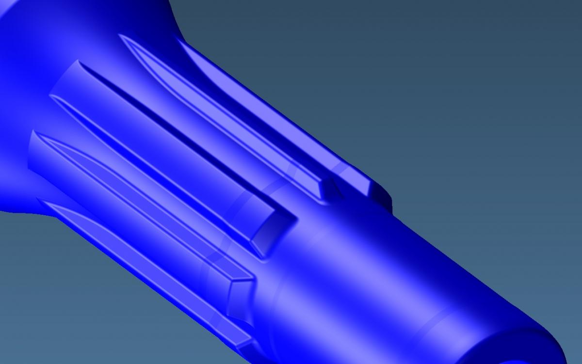
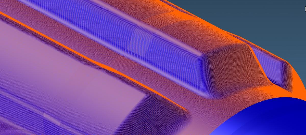
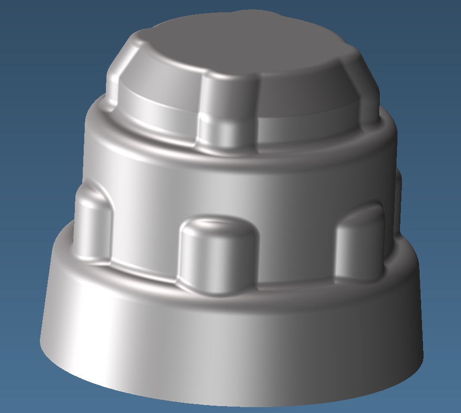
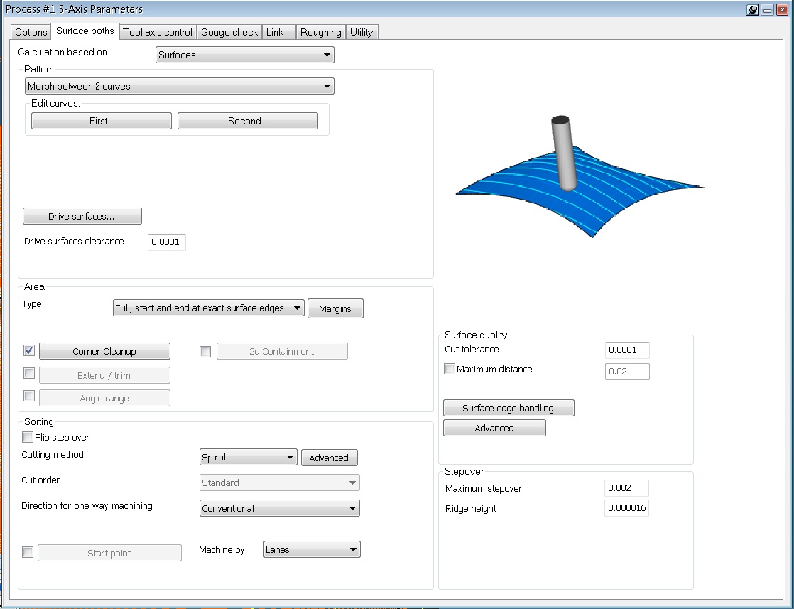
That machine looks familiar The following pics show an identical set-up on the same machine using a different CAM package with the same 5 axis module. Morph between curves works well in this scenario. Like Ron said though, busting your part up into multiple operations will produce a shorter cycle time and many more programming headaches. Too much compression in the corners here as well but this will get the tricky terrain done smoothly. Morph between surface can produce satisfactory results when morph between curves fails. Parallel cuts with spiral enabled works in a similar fashion. Bro, you have my email. If I can be of assistance, use it. Something to listen to while you check out the pics.


-
Welcome to the forum. The files are already posted. Page 10 or 11 of this topic will tell you how to gain access to the educational forum.
-
Anybody care care to chime in on the last post?
-
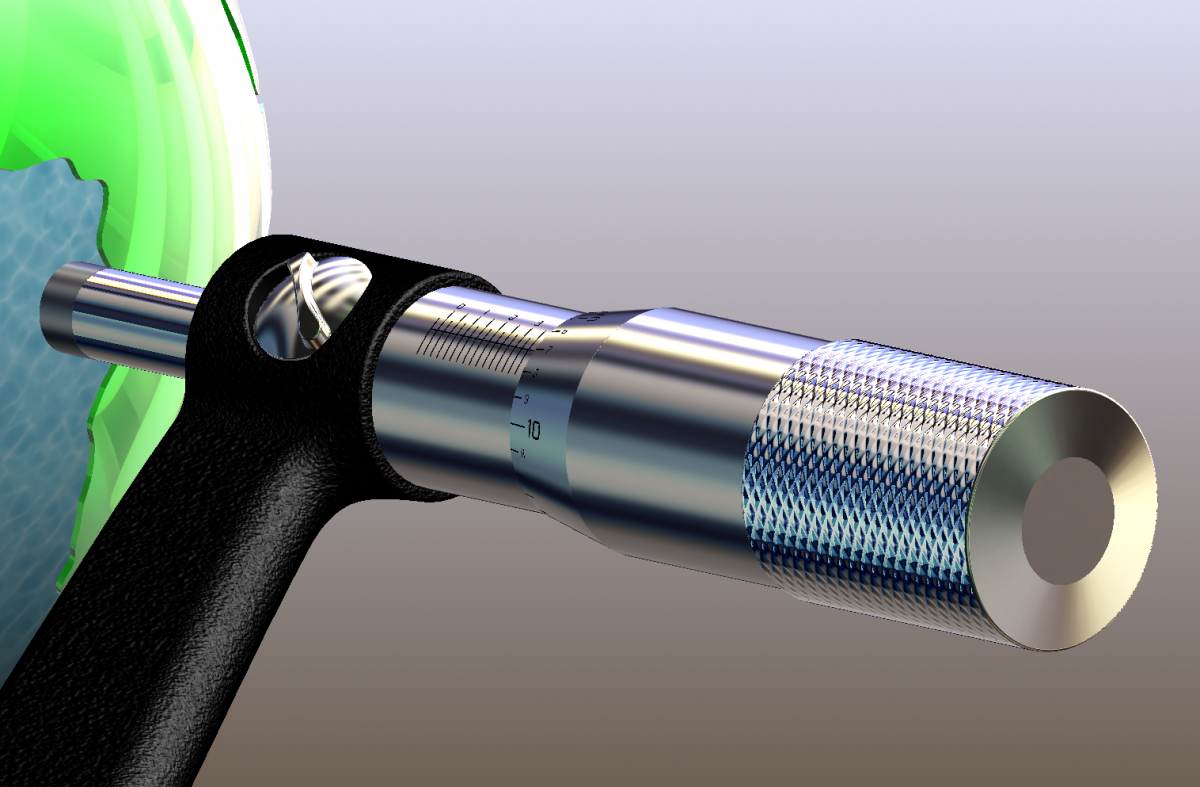
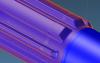
+1 to Solidworks. It takes more time but the results can be worth the effort. Make a circle or square that represents the size you need. Bring in the image, position it, size it and start tracing. You have much more control over curvature. Modeling it there would be the second step. Here's of few images traced, tweaked, or redesigned.


-
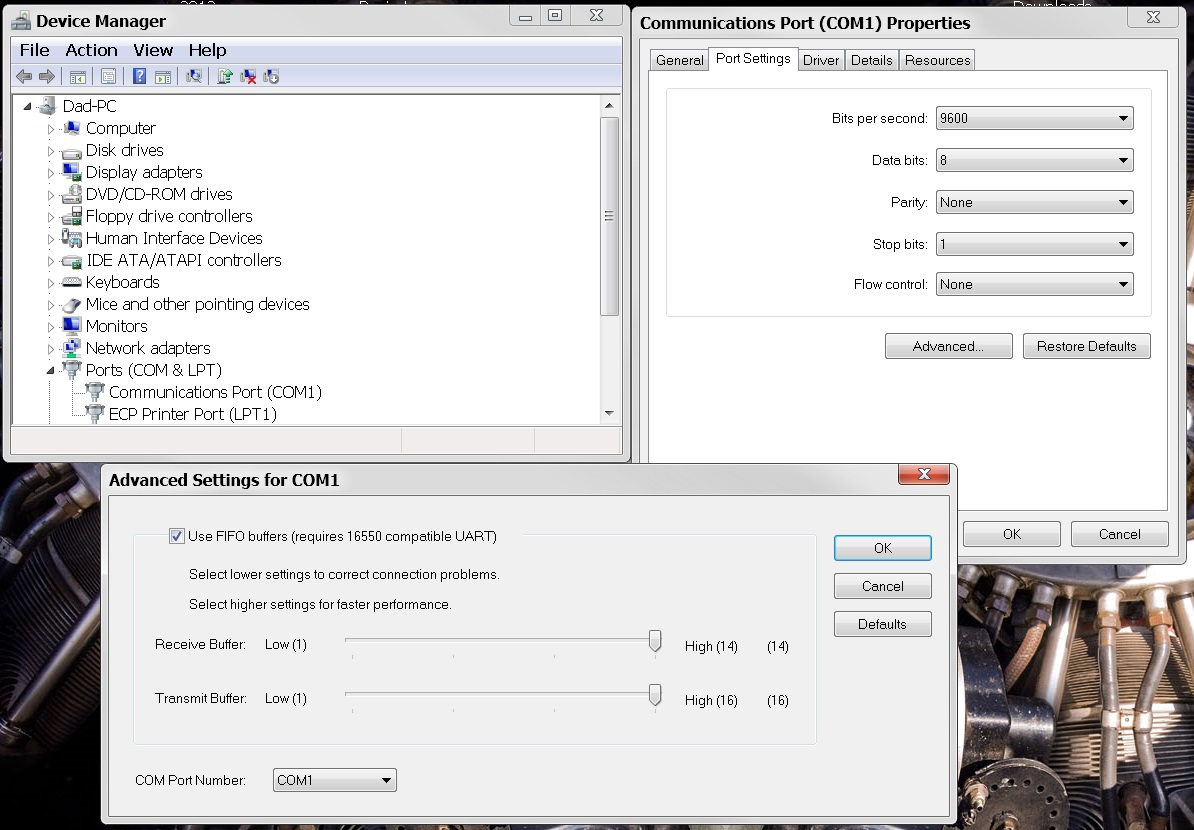
"My settings are what Minion's pic is." Just to clarify. Those are default settings on my home machine and do not match the Cimco or Haas settings at work. I was merely showing the locations in Windows. I don't use the com port on my home computer so I've never tweaked those settings. Look at the settings on the computer that does work and make the new computer match it. Also, your editor/transfer software have to match the comp as well. The Baud rate should be much higher than 9600. It's not uncommon to add a com port adapter inserted into a PCI slot. The new last new computer we purchased was a turd and needed it. Something like this: (Alan already stated this) http://www.amazon.co...ds=pci com port
-
Toolpathing a 3d part help!!!!
MotorCityMinion replied to lawrence walicki's topic in Educational Forum
Hmmm. Cool looking part. The color appears to be dull because of Zig Zag cut. Try one way climb. As for the tiny nicks. Tighten your tool path tolerance and use a smaller tool. Try using the arc filter to achieve smoother motion. You may have to use a different tool path strategy in this area to eliminate the nicks. I've had problems with Raster in the past. http://www.emastercam.com/board/index.php?showtopic=33276&hl=raster Another option: http://www.emastercam.com/board/index.php?showtopic=36121&hl=raster -
Did you take a look at these settings?
-
'"What can the multiaxis tool paths do for me that the surface and wireframe tool paths can't?" I just started using them and am no expert by any means. IMO, they are more more flexible. Entry exit moves and approach, how they handle multiple surfaces, ability to keep the tool down. There are more options for everything. When you get a decent understanding of the traditional 3 axis paths and their limitations then start using the multi axis, you'll know what I'm talking about. I wish I had started using them earlier. The flip side. There are more options for everything. A much higher learning curve is present. My current go to multi axis path is Morph between surfaces.
-
what is the main advantage of tangential approah
MotorCityMinion replied to tianle's topic in Industrial Forum
Both are the answer. Like he said,Too many factors to consider. Tangential eases into the cut. Make HSM more probable. Easier on the cutter and finishes as well. It can gouge just as easily. -
I've had the same issues with new comps. I changed the com port settings thru Windoze , Device manager I believe, and made sure both Cimco and the Haas were in sync.
-
"I was looking for answers to how the filters affect accuracy of the posted code. But it seems no one wants to comment on that.' O.K. I',m in. Filters of any type, on anything, arc or smoothing, always effect the code, and quite possibly in a dirty fashion. Set the tolerance to .00005. no arcs of any type, and you'll get as close as possible. Don't have room for code? That's a separate issue. Machine worn out? HA, everything else is mute. "That pretty much tells me I go for what gets the job done. It is what is it and if someone wants it faster then I tell them to take 100% responsibility for the part and show me a faster way. Getting it dialed in take trial and error and with 1 off parts I always did what I knew was 100% safe. Time is what it is." No BS here as I couldn't agree more.
-
Spending time at MCU will point you in the right direction. Thanks Jay. " Now I would of not use that path to finish that detail." I never cared for the shallow and flats option either. In a get er done mode, it's fine but it does leave something to be desired.
-
I don't have access to X7 but it sounds like your trying to cut shallow surfaces. If this is the case, Surface finish contour and Waterline behave the same way and are not suitable in these areas. These tool paths are based on step down and slice the model in Z steps to calculate the tool path so a shallow slope ends up having a wide step over. Best used with faces that are 30. to 90. deg. In a pinch you could change your step down then use depth limits to control the finish, using a deeper step down in a second tool path for the steeper faces. For horizontal faces, use HSM horizontal, SF Parallel, HSM raster or scallop. For shallow slopes or flat angular faces, use SF Parallel, HSM raster, HSM scallop, SF Flowline, SF Blend. Other options are available as well. Hard to advise without a picture though.
-
New to Heidenhain.
MotorCityMinion replied to MotorCityMinion's topic in Machining, Tools, Cutting & Probing
I've been meaning to get back to this post. Radial chip thinning and the Mikrons get along fine. We purchased the HSMAdvisor, set up our HP and torque specs, and successfully launched a new strategy for roughing and semi-finishing small parts on these machines.These machines are Ballerinas and excel 2360 IPM back feedrates / high feed, Granted if I need to take big chunks off, another machine gets the task. I've yet to get into setting up the machine or the day to day applications with the controls, as other chores are leading me down a different path but the tips in this thread are getting read. Thanks for the input. -
Cool looking part. Try not to include unnecessary operations in the stock model op. Drilled holes, small pockets, or any op not required to take you to the next station. If the current toolpath group can't see beyond the horizon or doesn't require all those faces for rest machining, leave em out.
-
The different collet types come in multiple sizes as well. The size or the Collar / cutter nut would be controlled by which type of collet, and what size.
-
This PDF was written as a safe approach and works without going into too much detail. "I only use 10% for toolpath radius with no probs. My original thought was that the tool would get into tighter corners with the smaller rad..." I've done 10% as well. IMO, with this setting, using aggressive feeds becomes speculative. I cut a lot of tool steel. When I do have to use 10% do get it to cut where I want it to, I re-evaluate the strategy and think about using a smaller tool in a second operation. Programming time, part quantity, and the amount of perishable tooling on hand now play into the equation. I also use stock set-up with accurate numbers. These Opti paths seem to have a mind of their own and accurate verify is a must.The boundaries give me that extra bit of control. As far as getting an exact start point, I've yet to do it consistently with Opti core. " I always click outside of this, not on a line or corner, and have always had the tool start where I have clicked." Newbeeee, I'll have to try that and revise the PDF. with you as a co author. I went back and tried a new tool path using this method, with and with out a boundary, containment center, containment outside, and it still stared where it wanted to. I think I'll have to start a fresh file and see if that helps. One slick trick that gives me more control is to use an extra large boundary and dummy drive surfaces in the model. An extra block here and there added to a copy of the model, then use the trim tool path op. Cuts the air balls out of the path and creates approach and exit mores closer to where I want them. Over in the Learning group section, there is a Gearbox Housing part that I worked on. Trim worked good in this scenario. Anybody that's interested should sign up, down load the file and take a look and comment. When using raw material with saw cut ends, I'll always set up a boundary that is larger by at least my step over. This keeps it safe and takes off some of the load with those first few corner rounding moves. People, keeps the tips coming!