MotorCityMinion
-
Posts
1,259 -
Joined
-
Last visited
Content Type
Profiles
Forums
Downloads
Store
eMastercam Wiki
Blogs
Gallery
Events
Everything posted by MotorCityMinion
-
V6.1 PRO
-
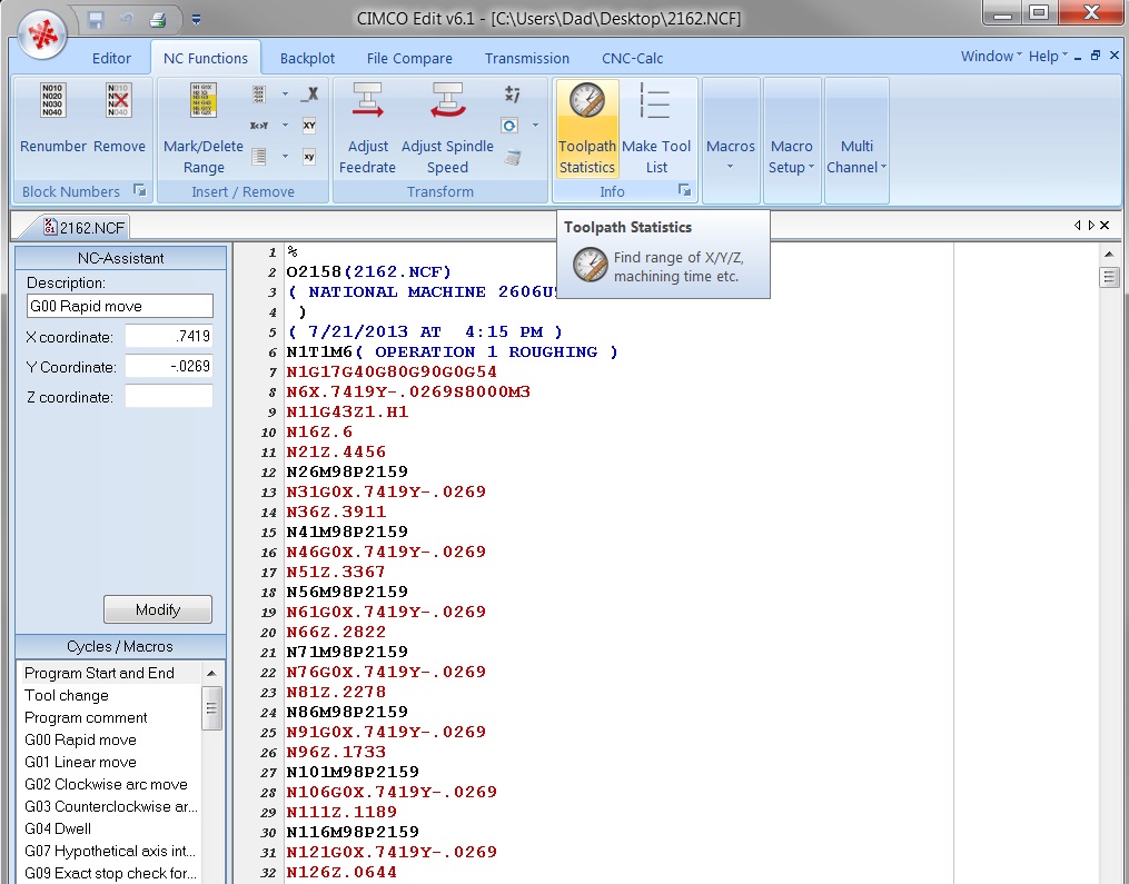
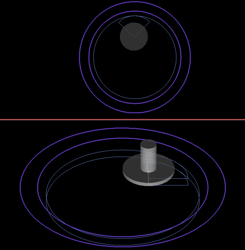
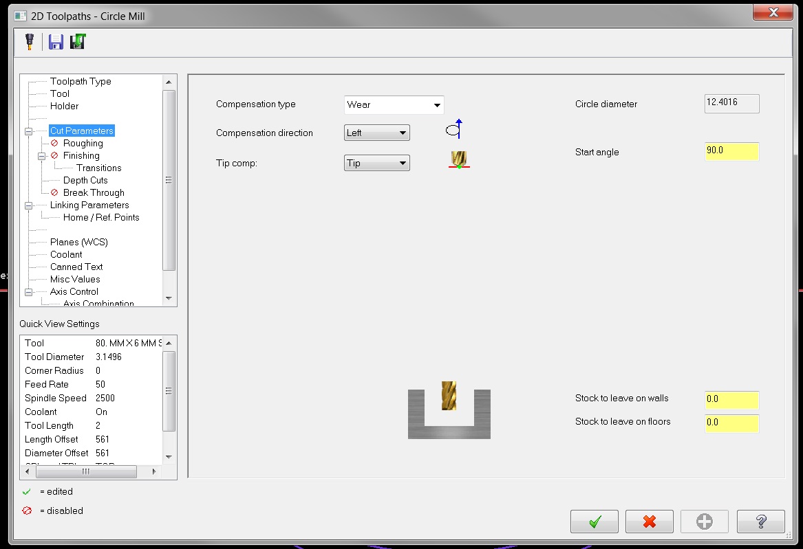
"The groove is cast in, i have to just clean the walls and bottom. I can write it by hand (??????) but i want to be able to use the wear offset to control my diameter dimensions." A simple 2d contour pass with multiple depth cut cuts will do this with wear very easy. Cutter = 80.mm x 6.mm Slot mill. Diameters as stated with a 11.98 wide groove. Finish pass at .2354 + 6mm cutter width + 11.98. Two cuts.
-
The latest version of Surfcam still has no Solids capabilities. My former boss used it, and despite all the negatives about the software that you may be reading about, he was able to crank out some very good looking code in short order. Crunch times seemed decent as well.
-
"I want to grow and grow big starting now. Any alternatives?" Your goals. Your future. Achieve them with Your new computer and X7.
-
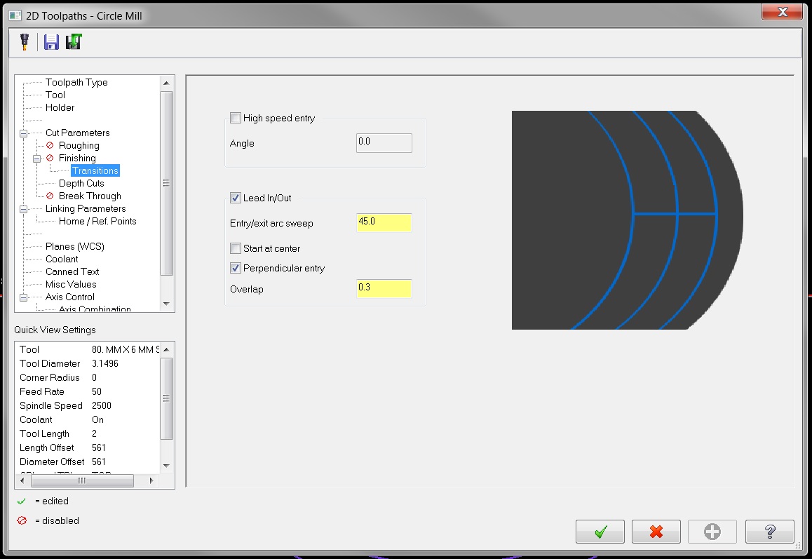
360 points, 180 points. What's with all the points? Machining splines gives crappy results anyway. Make 1 full circle, draw a single line through the circle at the angle you need to start your cutter at. Break at intersection then delete the lines. You could also just break the circle into multiple entities then Xform rotate everything the to the correct position for starting the cutter. K2 and Pilot pretty much nailed it. With a 2d circle tool path you don't even need a break, under cut parameters select your start angle, under finishing transitions you have your entry options.
-
I've found that in most cases splines will not trim to one another even if they do intersect. This message can be a bunch of malarkey: "selected objects do not intersect." If your lucky, you can extend both the splines, then use break at intersection and delete what you don't need. You can also make a new spline using the existing splines and loosen the tolerance.
-

Dynamic Core Mill - What the _ am I doing wrong?
MotorCityMinion replied to Bill H's topic in Industrial Forum
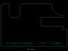
Since your Lavender chain represents your CLAMPS, portions of that need to be included in Avoidance region. Sorry about the confusion. See the pics. Typically, I separate the chains by raising or lowering the Z, of either chain. This eliminates branch points when selecting the chains. Under linking parameters, set your clearance higher than the clamps and shut off retract. I'm not sure how you chained those entities to get those results in the MCM file, but that tactic may actually work in a different part scenario.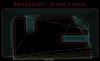

-
Dynamic Core Mill - What the _ am I doing wrong?
MotorCityMinion replied to Bill H's topic in Industrial Forum
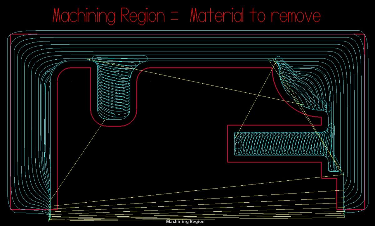
Here's where the confusion sets in. The Avoidance region is actually what you want to machine. Think of a simple 2d contour around a part. You select the chain, tell it how much stock to leave and so on. Obviously if you needed to stay out of a certain area, you would not select the entire part perimeter, you would just use a partial chain or an entire, non-closed chain. With Dynamic milling, the avoidance region would be the same chain you selected in the old school 2d contour path but is typically closed, avoiding this chain by the same value you would have entered in the old school tool path. The stock (Machining Region) defines the raw amount of material to be removed and the cutter only works in this region. Because your Stock overlaps your clamping area and the entire part, it's going to try and machine around the entire part profile and through your clamps to get rid of this material. Notice the word region. The cutter can and usually does roll around the corners of the stock so pay attention. In your case, get rid of the Lavender chain all together. Copy your part profile, which is your Avoidance region, to the level where the stock profile is. Shut off the part profile level and take the lowest line out of the copied part profile. Extend the two lines (outside edges in X) on the part profile and trim them to the Stock boundary. Trim the stock boundary (Machining Region) so that it does not cover or include your clamps in this area. It should look kind of like a horse shoe. They really need to rename the Avoidance region to something better suited to the goal of the task at hand. This link may help some. http://www.emasterca...opic=73252&st=0 -
"I think from here on anyone wanting in should program the Idler bracket in this thread and submit it. What do you guys think? That part is a little tough for the noobs. Any part for a totally new guy can be rough.
-
"But thanks for the tip about the quick masking. I never really used them, but that seems like a handy feature." Force yourself to learn and use this feature for the next dozen jobs. One of my favorite tools for sure.
-
Brandon, go grab a few a of the different Jazz bass files. That and the unofficial Idler Bracket are very good examples of how different techniques can be applied to the same part. The Gearbox Housing is a real challenge for intermediate users and I'm looking forward to seeing more of those files soon.
-
New to Heidenhain.
MotorCityMinion replied to MotorCityMinion's topic in Machining, Tools, Cutting & Probing
Good info guys. I grabbed a few of the manuals off their website. I need to get to the manuals at Mikron as some of the keys are located in different spots on the control. Hardest part is trying to decipher what it's asking me to do. It'll come though. Dwain, I just may take you up on that offer. They don't do adaptive clearing / dynamic milling here and I want to demo that for them successfully. I'll get some data from you when the time comes. Thanks guys, keep em' coming. -
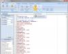
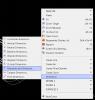
This is fairly typical of what I use. Eventually I'll get annoyed this layout and redo it.
-
New to Heidenhain.
MotorCityMinion replied to MotorCityMinion's topic in Machining, Tools, Cutting & Probing
Ron, thanks for the tip. I found the manuals in the control and uploaded them. All our probing cycles are written into the program. This is really my first experience with probes and all I can say is WOW. It's a 5 axis and bada$$ at what it does. No real balls and we can't really rough with it. Hard milling at 40k, sweet. Still looking for forums and videos. Keep the tips coming! Tony, thanks for the offer. Thanks for your time, MCM. -
I just started a new job that uses MIKRON HSM 400U LP Machining centers. Cool machines BTW. It has a Heidenhain iTNC 530 control. This control might as well be set-up in Arabic as there are very few similarities to a Fanuc. The Heidenhain website is hideous to navigate. What I'm looking for is forums, websites, videos, tips & tricks info, anything in English to get me going with the control and probing. ANYTHING would be greatly appreciated. Thanks in advance, MCM.
-
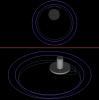
Ok, I have the same book. It's the thing that looks like a tape dispenser. This worked fine for me using the splines. Be sure to select your chains in the same general area, lets say both ellipses in the upper left quadrant, inside, chains going the same direction. Both ellipses in the lower right quadrant, outside, chains going the same direction. Any area will work as long as both chains are selected in the same fashion. Oops, wrong entities. give me a few, I'll do the cut. Chaining the rectangles in the same fashion as above and selecting cut from the options menu worked fine here.
-
'I have completed mill 1 and mill 3 tutorials, am on solid #5. " What version Mastercam and what book with which tutorial number are you asking about?
-
"What does the opti rough do that's different from the are clearance?" It uses the full flute length of the tool. Think end mill. You also get to add the chip thinning factor and bump up the feed rate. Program both paths and see the difference. What material?
-
If your only roughing that one side in a separate op, then djstedman had the answer. Taper wall in 2D contour. If you want to rough the entire perimeter of the part in one op, create an extruded surface that mimics the wall profile with a draft and include that in your drive surfaces.
-
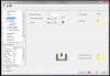
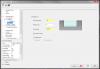
OK. I was using the default set-up sheet in the HLE, which btw, is fairly decent. The gnome shows up in the stock set-up view, not the machine view and I did not see it until I created a set-up sheet in ISO view. I don't know if the Verisurf add on works with the HLE. May be I'll mess with it some after I finish my next project.
-
Jay. How did you get the gnomon triad to show up? I tried it in the HLE, flipped a few switches, and nothing happened. Even set display to wireframe.
-
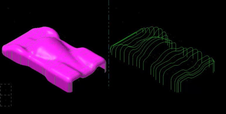
"It would not hurt at all to learn both complex shapes in MC and also Inventor" Very wise. If your next employer only has MC, you'll be that much further ahead. Autodesk has been on a acquisition mission over the last few years and things are looking good with regards to capabilities. I actually learned more about Solid modeling by working with SolidWorks. This gave me insight on what not to attempt in MC or why I should model in MC. After using a true CAD package for awhile, you'll be able to look at a print and decide which app to use right away. As with anything worth doing, the more complex the app, the longer the learning curve. Some simple parts actually require more data input to get it done in SW or Inventor. To many bells and whistles. IMO, simple parts are just much faster in MC. My preference is MC first, no import or conversion errors and I have a history to work with. I came came across a lofting tutorial in MC, of a car body with quite a few curves in it. Mastercam chained it in one window with a start point. The chain geometry was iffy and surfaces less than perfect but it still produced a shape that could be worked with. SolidWorks gagged on it when attempting to do it all in one hit. See the picture.. The Mastercam version took less than one minute to complete. Trying the same method in SW failed. The SW version took about an hour. I had to split it in half, correct any funky geometry, create splines to drive the loft, using the existing MC geometry as guide curves, create the surface then mirror it. One surface did it. Over a couple of hundred clicks I'd say. Marginally smoother surfaces but much more work. If I had used boundary surfaces for the individual segments, I could have pulled off more curvature continuity, add another hour and a couple of hundred mouse clicks. It really depends on your requirements as this is an apples to oranges comparison.

-
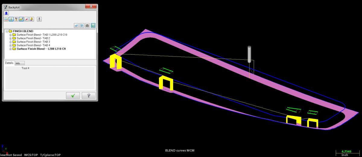
Nice part. Big one also. As for the marks your pointing to. The tool path tolerance can influence this. How tight the machine is (back lash) plays a major role as well. Sudden or sharp direction changes can produces less than satisfactory results. Scallop tool paths really exhibit this condition. Tangential linking moves in HST tool paths will reduce these occurrences. The first file that was uploaded had a gap setting of 10.00" in the tool path. In areas of the surface that are shorter than this, the tool was actually back tracking on the surface to get to the start of the next cut. Add up all the variables and you can get what was shown in the picture.
-
Surfacing from a Point 4th axis.
MotorCityMinion replied to NOTW Programmer's topic in Industrial Forum
"P.S. Why cant we overwrite our files on the FTP !" Individuals with devious intentions could alter the files.- 28 replies
-
- 1
-

-
- Surfacing
- From a point
- (and 2 more)
-
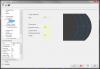
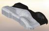
Not too shabby. I untrimmed the surfaces. Just extend / trim your blend curves to suit your needs. BLENDHELP MCM.EMCX-6 FTP: X6 _FILES