


Rstewart
-
Posts
754 -
Joined
-
Last visited
-
Days Won
4
Content Type
Profiles
Forums
Downloads
Store
eMastercam Wiki
Blogs
Gallery
Events
Everything posted by Rstewart
-

Call out X,Y plane after toolchange
Rstewart replied to Rstewart's topic in Post Processor Development Forum
I got it :) I had to add an *sgplane in the string pcan1, pbld, n$, [if gcode$, *sgfeed], *sgcode, *sgplane, *sgabsinc, pwcs, pfxout, pfyout, pfcout, *speed, *spindle, pgear, [if gcode$, *feed], strcantext, e$ Now I get a plane callout on every toolchange line -
Call out X,Y plane after toolchange
Rstewart replied to Rstewart's topic in Post Processor Development Forum
Yeah, all that did was add a G17 in the code before every retract. I just need it called out right after the toolchange. Like G0 G90 G17 G54 X0. Y0. M3 Etc Etc. -
I got bit by the sideways drilling spotdrill yesterday lol. After running an engraving path on the rotary the next tool up was a spot drill using G81. Well, turns out still having G19 active is really eye opening. I used to run MPmaster post witch would call out the sgplane at every toolchange. I'm using another one that works with CIMCO probing now that doesn't post out a G17 at every toolchange. I've looked at the Mpmaster and can kinda see how it works, but I thought I would ask here. I can go back to my reseller for the update, but I always like to learn more about posts myself. Thanks in advance for any of ya'lls time
-
I knew there was something I was missing. Thanks again man
-
This *Should* be Very common, how else would you tackle multiple parts in a VMC? Two vises, two parts. I'll get this sent off to QC at mastercam
-
Thanks for checking it out. Btw, it also does this behavior on two other toolpaths. What is my usage of transform that you've never seen before?
-
Toolpath #4 is the problem child PIF35232_03.mcam Btw this is MC 2023 update1
-
Well, I have one for QC.... Two parts, g54 g55. I hear the finishing 3/4 endmill making more noise than it should be. I go through the code and found the issue. On one operation (simple contour) it runs that path Twice on the G55 and never even calls out G54. I have checked everything I know twice. Does anyone here wanna check it out??
-
Man, all I know is I used the option to disable paths/ghost and create separate (or whatever it's called). I've used it many times before, but I'm unsure of what could have happened?? Now I'm scared to use it. It left off a 3d horizontal floor finish path and simple contour. It may very well have been my fault, but I'm unsure of how or what...
-
Toolpath transform bit me today.... All seemed to post out correctly, But two paths failed to end up in the code Didn't realize this until after the parts were off the machine. This was just for g54 and g55 in two separate vises. Could have been BAD.
-
Do any surfacing toolpaths support lollipop tools???
Rstewart replied to jaydenn's topic in Industrial Forum
I had to make some parts recently like the garbage above out of SS on a 3axis. I window framed the part out of plate so I could "index" it in the vise and have a reference point. Worked great, except was Slow. Unless there's something I'm not seeing, there's no need for a lollipop tool? -
Facemill for 4140 prehard to ~40-45RC
Rstewart replied to rgrin's topic in Machining, Tools, Cutting & Probing
Mitsubishi WSX 445 with one wiper insert installed. 16 finish no problem -
Dude, it's a Bow frame.... If everything is relatively flat and true I would Assume ±.02 would be fine lol. But then again I don't machine archery products....
-
Programming Tip - Helix Bore "depth cuts" - Faster solution?
Rstewart replied to ThickChips's topic in Industrial Forum
Ron, could you elaborate a lil more? I understand the misc int are customizable, but how exactly would that work? I may would like to incorporate something like that in our post. -
Programming Tip - Helix Bore "depth cuts" - Faster solution?
Rstewart replied to ThickChips's topic in Industrial Forum
When that posts out it's not calling up the spindle after the M00, some machines may not work like that. You can fix this by checking "force tool change" in the first op. This will send Z home though... -
What post are you using? What version of MC?
-
What version of MC? What are your computer specs? How are you attempting to create the plane?
- 1 reply
-
- 1
-

-
Internal radius on a slotted pipe, 3/4-Axis
Rstewart replied to CNC programming questions's topic in Industrial Forum
G helped me with this years ago. Like Leon said, Lollipop mill and model an inside radius > surf fin contour > gouge check off > direction for getting in and out. -
I will be happy to report that my Reseller has been very responsive to my requests. He is working on it and I'm sure they'll make it right. Just wanted to say this as most of the time you only hear negative press "reviews". I like to report the good a company is doing.
-
I have reached out and they are working it. In all reality I'd just like to incorporate the CIMCO and the HAAS machining modes (G187 modes) into my current Mpmaster post...
-
What's up guys, So we've purchased the cimco probing package and it's great, really saves time from writing macros at the machine. We've received a haas 3/4 axis post to use that will work with the probing add-on from our MasterCam reseller. I've always used Mpmaster and just dabbled in modifying posts over the years. I do not agree with how this post is outputting code for the probing routines - It doesn't limit block look-ahead with a G103 at all... This post does have the haas G187 P and "E" values in the Misc. values page, which is nice. Unfortunately, if you select the checkbox "automatically set to post values" you get a G187 code in your probing routines - No good IMHO. Is there an easy-ish way to fix, or better these issues. I can ask my reseller, but I'm doubting they are willing to fix this, I mean they did supply the post and stated it was good to go.
-
The easiest way is probably going to be surface rough parallel or area roughing. You'll need to draw a containment boundary, then just select the whole solid. I would semi-finish with raster most likely.
-
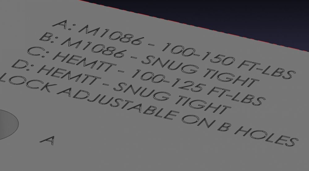
In my experience Using the "engraving toolpath" for regular numbering/lettering w/ a ballnose EM just kinda Sucks. Maybe I'm doing it wrong? When you use the create letters tab in MC > contour > window select geo > compensation OFF > Done.... But you have to create geometry and screw around sizing/placement. I was just curious if someone had a trick on engraving right from the solid (models created in SW). This, for instance is something I get all the time.
-
Yeah, I've done that as well. If you want to engrave on C/L (comp off) you have to create curves, then offset every curve, perpendicular half the distance - No bueno. If only there was a way to drive C/L off the solid extrusion...
-
Hey guys, One of the newer guys here was asking how I go about engraving lettering on Solidworks models that have text extrude cut into it. I have always just created letters (box font) approximately over the solid lettering. Some of these parts have a good bit of engraving, is there a faster, easier solution out there?


