


wdg5555
-
Posts
90 -
Joined
-
Last visited
Recent Profile Visitors
1,128 profile views


wdg5555's Achievements
")
Newbie (1/14)
20
Reputation
-
If geometry is independent then how do you explain the video below? edit: nevermind. Just realized you said "3x paths". I don't have multiaxis option btw.
-
I've tried both ways and Its slower to have your wireframe and solid on different levels. Is it alot of wasted time? nope.
-
I use levels for every job I do. I just prefer to have the wireframe and solid on the same level. Can anyone answer my questions in the original post? Not sure what you are talking about.
-
I'm using 3x drilling using the same WCS on all toolpaths and the T and C planes set to the angle I am working on. I don't think drilling toolpaths are controlled by the tool planes unless they have changed something since X6. This can be confirmed by selecting a point instead of a circle entity in the drilling toolpath. As far as I know selecting points instead of circle entities will cause issues. Turning off shading still results in the ability to select solid geometry in a drilling toolpath. I don't want my wireframe and solid on different levels.
-
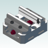
I'm guessing this has been asked before but I couldn't find it. If you look at the attached pictures you will see the same drill path but one has circles selected for the drill entities and the other one has solid geometry selected. When the solid geometry is selected the drill does not drill at the correct angle (this is for a rotary). My questions are, 1. Why does it drill at the wrong angle when solid geometry is used? 2. How does one correct this issue? 3. Is there anyway to select circles only and not 3d geometry when the circle and 3d geo is shown at the same time? In other words I would like the option to not select 3d geometry when selecting entities in a drilling toolpath. Thanks! New Bitmap Image - Copy.bmp New Bitmap Image.bmp
-
I did something similar to this awhile back. I remember thinking I did something that could have been done better but I don't remember what it is right now. Below is the code I added to my post. It doesn't say Leave stock. But at the beginning of each toolpath it lists the stock left that is programmed into mastercam. You can adjust from there. Here is what the beginning of my toolpaths look like. N1( 1/2 FLAT ENDMILL - T1 - D1 - H1 - .5) (Control) (XY Stock .005) (Z Stock 0.) In the variables section add below fmt "XY Stock " 2 xystockwdg fmt "Z Stock " 2 zstockwdg Under psof section add below if opcode$ < 3 | opcode$ > 3 & opcode$ < 14 | opcode$ > 17, [ rd_prm_op_no$ = op_id$ rd_params$ "(", *scomp_type, ") (", *xystockwdg, ") (", *zstockwdg, ")", e$ ] Under pparameter add below if prmcode$ = 10010, xystockwdg = rpar(sparameter$, 1) if prmcode$ = 10068, zstockwdg = rpar(sparameter$, 1)
-
What is the xtooltable? Is it in the new posts?
-

Post Retract end of G71 Canned Cycles?
wdg5555 replied to R_Hawk_one's topic in Post Processor Development Forum
I knew my suggestion would not go over well But this avoids having to setup stock. The little bit I have used stock it is a pain to use. And even if its not a pain to use its still an unnecessary /extra step to do. Additionally what happens if you program a boring bar and you forgot to setup your stock or your reference points? CRASH! My post edit is foolproof, which the less I have to use my brain the better my day seems to go. -
Post Retract end of G71 Canned Cycles?
wdg5555 replied to R_Hawk_one's topic in Post Processor Development Forum
I setup my lathes posts to go to Z1.0 at the beginning and end of every tool path. This works as long as your Z zero is always at the front of the part. You could make a variable to add 1" to the zabs variable if your Z zeros are not always at the front of the part. Only time I have to hand edit is when I use a tailstock, which is rare for me. And the best reason for doing it this way is you don't have to setup stock or reference points. Below is the code I use, you will have to pull up the debugger most likely to figure out where exactly to put this in your post. In section ltlchg$ "G0", pfxout, "Z1.0", e$ In section pl_retract$ "G0 Z1.0", e$ -
Okuma ID thread turning critique
wdg5555 replied to mkd's topic in Machining, Tools, Cutting & Probing
.01 depth of cut is a very safe starting point for 1/2 threads. Which i believe would be a "D.02" since okuma lathes use diameter instead of radius. It also looks like in your program that your starting the first cut at x.2653. This Should be the minor diameter of the thread. Check when your threader is actually cutting in X. I'm guessing there is a lot of air passes. -
The problem was using the variable force_tlchg$. I found the parameter 15108 which also looks at the force tool change button. Then captured it in pparameter and it now it works.
-
I'm trying to get an error to pop up during posting when force tool change button is not checked. Below is the code I am using. if force_tlchg$ = no$, result = mprint(swdgftchg) My problem is I can't find a good place to put it in the post where it correctly gives me the error when the tool change button is not checked or it gives me the error when the button is checked. I've tried ptlchg, ptlchg0, and the pwrtt sections. It seems the variable force_tlchg does not work as I think it does. I'm using the generic 5x post. Closest I came was it would correctly give the warning with drilling cycles but for some reason not on milling toolpaths.
-
If your speeds are really slow you might want to check your setting in Hi-Cut parameters. The number under maximum feedrate controls the maximum feedrate regardless if you are using Hi-cut or not.
-
Ya Colin's posts above are correct. I never should have questioned it.
-
You will have to re-read Colins post to figure out exactly where to put this code since our posts are different. Remember to backup your post before you try to make changes Put the below code with the other variables near the top of the post. swcswdg : "" swcswdgchk : "" Add Below code to section ptlchg1002$ if swcswdg <> swcswdgchk, #check for multiple wcs [ result = mprint(swdgwcschk) swcswdg = swcswdgchk ] Add code below to PSOF section swcswdg = swcswdgchk Add code below to pparameter$ section if prmcode$ = 20014, swcswdgchk = sparameter$ #check for multiple wcs Add code below to custom errors section swdgwcschk : "WCS is inconsistent. Verify WCS is correct in toolpath."
