Bill H
-
Posts
171 -
Joined
-
Last visited
Content Type
Profiles
Forums
Downloads
Store
eMastercam Wiki
Blogs
Gallery
Events
Everything posted by Bill H
-
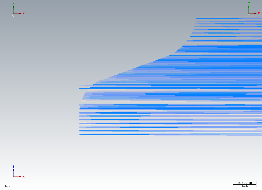
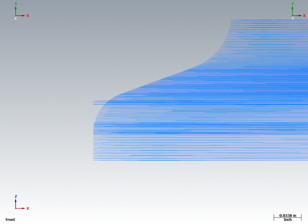
byte me: I made a new swept surface by adding short straight sections at the top and bottom. Then I tinkered with Depth Limit settings and that made things work well in the +Z area. In the -Z area, however, I'm getting a gouge that I can't get rid of (see image below). Any ideas? The latest file is attached. Thanks again! Undercut surface.mcam
-
byte me: Wow. Thanks for all of your effort on this! I'm not quite sure I understand it all yet, but let's see what I can do.
-
Please have a look at the attached file. I've been beating my head against a wall for hours trying to get the undercut (Operation #9) to work properly. Depending on settings (I've tried many), either the tool doesn't fully cut the profile or it gouges. What am I doing wrong? The -Z portion of the profile (Operation #8, not undercut) works fine. MC2018 2.5 axis. Thanks! Undercut_surface.mcam
-
Leon82 - Thanks! That seems to work fine. AMC Nitro - Thanks for the response, but I don't understand. The first segment of the toolpath I was working with was a short straight segment and then there was an arc. Is this something different than what you're suggesting?
-
I work with a lot of smaller equipment and really like the Ramp Contour for milling larger holes. My problem is that MasterCam inserts the G41/G42 code on an arc move with this toolpath. Since this is a Bozo no no for our Haas mills, we're not able to fine-tune the hole size at the control by entering a wear value. Is there some way to get MC to put the G41/G42 code on the linear part of the lead-in move? Thanks!
-
JParis - Perfect! Many thanks!
-
The title says it all. I'm working with MC 2019 and 2024 aluminum comes up as the default material. I'd like to change this to 6061 aluminum. How do I do it?
-
JParis - The problem with doing it this way is that if I now change the 2" Retract to 3", the Jump height stays at 2". In other words, for the point where the 'Change at Point' was applied, it doesn't seem there's a way to undo the change and get the changed parameter to follow the Linking Parameters values - other than your suggestion of re-selecting the point.
-
JParis - That's the only method that I've found that works reliably. I was hoping there was a simple 'undo' or 'restore defaults' option.
-
I'll be more specific. Let's say the toolpath has ten points and I've set the retract value to 0.1" absolute. To avoid a clamp, I use Change at Point and put in a jump height of 2.0" at point #4. Whoops - I meant to use the jump height at point #6. How do I remove the change that I've put in at point #4? If I put in a value of 0 for the jump height, this overrides the retract value. I'm looking for a 'do over' - a way to get rid of my changes and return all parameters to their original values.
-
In a drilling toolpath, I've used the 'Change at Point' functionality to alter the parameters at several points. How can I undo these changes and return to the default values? MC2019
-
Cutter Comp Beginning on Arc Move - How to Avoid?
Bill H replied to Bill H's topic in Industrial Forum
Here's an example of what I'm talking about. I've created a sample program using the Circle MIll toolpath to rough mill a circular pocket that's 1.00" in diameter and is 0.50" deep. I'm using a 1/2" diameter endmill and wear comp. The G-code, as generated by MC's generic Haas post is: O1001 (CIRC MILL TEST) (DATE=DD-MM-YY - 22-06-19 TIME=HH:MM - 14:23) (MCX FILE - T) (NC FILE - C:\USERS\BILL\DESKTOP\CIRC MILL TEST.NC) (MATERIAL - ALUMINUM INCH - 6061) (T8|0.5 FLAT ENDMILL, 3-FL., CARBIDE|H8|D8|TOOL DIA. - .5|WEAR COMP) N100 G20 N110 G0 G17 G40 G49 G80 G90 (CIRC MILL 1" HOLE NO FINISHING) N120 T8 M6 N130 G0 G90 G54 X-.1645 Y-.1535 A0. S6112 M3 N140 G43 H8 Z.25 N150 M8 N160 Z.05 N170 G3 X0. Y-.225 Z.0403 I.1645 J.1535 F73.3 N180 X.225 Y0. Z.0218 I0. J.225 N190 X0. Y.225 Z.0033 I-.225 J0. N200 X-.225 Y0. Z-.0152 I0. J-.225 N210 X-.1645 Y-.1535 Z-.0241 I.225 J0. N220 X0. Y-.225 Z-.0338 I.1645 J.1535 N230 X.225 Y0. Z-.0523 I0. J.225 N240 X0. Y.225 Z-.0708 I-.225 J0. N250 X-.225 Y0. Z-.0893 I0. J-.225 N260 X-.1645 Y-.1535 Z-.0982 I.225 J0. N270 X0. Y-.225 Z-.1079 I.1645 J.1535 N280 X.225 Y0. Z-.1264 I0. J.225 N290 X0. Y.225 Z-.1449 I-.225 J0. N300 X-.225 Y0. Z-.1634 I0. J-.225 N310 X-.1645 Y-.1535 Z-.1723 I.225 J0. N320 X0. Y-.225 Z-.182 I.1645 J.1535 N330 X.225 Y0. Z-.2005 I0. J.225 N340 X0. Y.225 Z-.219 I-.225 J0. N350 X-.225 Y0. Z-.2375 I0. J-.225 N360 X-.1645 Y-.1535 Z-.2464 I.225 J0. N370 X0. Y-.225 Z-.2561 I.1645 J.1535 N380 X.225 Y0. Z-.2746 I0. J.225 N390 X0. Y.225 Z-.2931 I-.225 J0. N400 X-.225 Y0. Z-.3116 I0. J-.225 N410 X-.1645 Y-.1535 Z-.3204 I.225 J0. N420 X0. Y-.225 Z-.3301 I.1645 J.1535 N430 X.225 Y0. Z-.3486 I0. J.225 N440 X0. Y.225 Z-.3671 I-.225 J0. N450 X-.225 Y0. Z-.3856 I0. J-.225 N460 X-.1645 Y-.1535 Z-.3945 I.225 J0. N470 X0. Y-.225 Z-.4042 I.1645 J.1535 N480 X.225 Y0. Z-.4227 I0. J.225 N490 X0. Y.225 Z-.4412 I-.225 J0. N500 X-.225 Y0. Z-.4597 I0. J-.225 N510 X-.1645 Y-.1535 Z-.4686 I.225 J0. N520 X0. Y-.225 Z-.4783 I.1645 J.1535 N530 X.225 Y0. Z-.4968 I0. J.225 N540 X.2169 Y.06 Z-.5 I-.225 J0. N550 X0. Y.225 I-.2169 J-.06 N560 X-.225 Y0. I0. J-.225 N570 X0. Y-.225 I.225 J0. N580 X.225 Y0. I0. J.225 N590 X.2169 Y.06 I-.225 J0. N600 X0. Y.25 I-.253 J-.07 N610 X-.25 Y0. I0. J-.25 N620 X0. Y-.25 I.25 J0. N630 X.25 Y0. I0. J.25 N640 X0. Y.25 I-.25 J0. N650 X-.25 Y0. I0. J-.25 N660 X0. Y-.25 I.25 J0. N670 X.25 Y0. I0. J.25 N680 G41 D8 X0. Y.25 I-.25 J0. N690 G0 Z.25 N700 G40 M5 N710 G91 G28 Z0. M9 N720 G28 X0. Y0. A0. N730 M30 % Note that cutter comp is invoked with an arc move on Line N680 which, of course, results in the machine having a nervous breakdown. How is it possible to use the Circle Mill toolpath with no finishing passes and avoid this? -
Cutter Comp Beginning on Arc Move - How to Avoid?
Bill H replied to Bill H's topic in Industrial Forum
Sorry, I should have been more specific in my original post. In the circle mill toolpath, you cannot use just a roughing pass, unless the diametral wear value in the control is zero because MC is invoking the comp on an arc move. This is also true with thread milling ID threads, but fortunately in this case MC provides some lead-in/lead-out options to eliminate the problem. I suppose the heart of my question is whether there's some setting that would prevent the invoking of comp on arc moves. -
I do most of my programming with Wear cutter compensation. Unfortunately, MC has a nasty habit of invoking the comp on an arc move, which on our Haas mills triggers an alarm and shuts down the program. What's the best way of getting around this?
-
Is there a way to edit tool definitions other than the "Edit Tool" Command? I was hoping for some sort of database or spreadsheet solution. I need to edit a lot of tools and doing them one at a time with Edit Tool is just too slow and cumbersome.
-
Jason - yes, the error happens only with solid chains.
-
A popup saying "Error - Auto Orientation Failed" appears whenever I try to change the start point of a contour toolpath. This only began recently and I have not made any changes to my installation. Any ideas how to fix this? MC2019.
-
Cut Direction - Multisurface Rough Pocket Toolpath?
Bill H replied to Bill H's topic in Industrial Forum
Codeworx - You win the gold medal! Now my toolpath does just what I want it to. -
Cut Direction - Multisurface Rough Pocket Toolpath?
Bill H replied to Bill H's topic in Industrial Forum
Seedy Steve - Yes, I've tried the entry point option. The tool will enter at this point, but then immediately rapid over to a point next to the surface I'm trying to machine. -
Cut Direction - Multisurface Rough Pocket Toolpath?
Bill H replied to Bill H's topic in Industrial Forum
AMCNitro: I only have Mill level 1, so OptiRough isn't available to me. -
I'm using a Multisurface Rough Pocket Toolpath to rough out an irregularly-sloped face on a rectangular block. I would like the tool to start outside the stock and move inwards toward the sloped face. Instead, it starts next to the face by cutting a slot and then moves away from the surface towards the stock boundary. How can I change this? MC2019.
-
A minimum feed for arc moves can be specified on the Tool Settings tab of Machine Group Properties and this setting is applied to all operations within that machine group. Is there a way to make the setting apply only to specific operations?
-
mkd: Thanks for your replies! Yes, I'm running this on a Haas mill with a Haas rotary. nickbe10: Thank you! I'm not sure what you mean by 'derived geometry'. Please explain.
-
I'm working on my first project with a rotary table and am way confused. Can someone have a look at the attached files and tell me what I'm doing wrong? The idea here is that the formed tube fits on a mandrel that's mounted to the rotary table. The tool's Z-axis intersects with the part's X-axis (and the rotary table's axis). As the rotary turns, the part moves along the X-axis to cut the 'scallop' feature at the end of the tube. I have several problems: 1) Look closely at the toolpath and you'll see that it doesn't make a full 360-degree rotation around the part. Why? 2) The first part I cut was terribly faceted. What settings should be changed to control this? 3) Note in the G-code that the initial position of the toolpath is at approximately 180 degrees. How can I get this position to be 0 degrees? 4) Where are those crazy feed rates in the G-code coming from? 4 AXIS CYLINDER.mcam 4 AXIS CYLINDER.NC
-
Smit - Thanks! That worked great.