


motor-vater
-
Posts
379 -
Joined
-
Last visited
-
Days Won
4
Content Type
Profiles
Forums
Downloads
Store
eMastercam Wiki
Blogs
Gallery
Events
Posts posted by motor-vater
-
-
19 machines give or take
8 - 3 axis mostly with rotary's
5 - horizontals
6 - 5 axis
All Mills All the time
We have lathes to but I got a guy for that
-
 3
3
-
-
IM THE MACHINE NOW!

-
 5
5
-
-
3 hours ago, Sigurd said:
It would be nice. I've noticed that on OptiRough and Area Rough where the cutting motion is fine, but the transition/linking motion shakes the machine.
Possible from linking motion being speed up? chocking on code?
-
I see the same behavior on our haas's all the time. I could say some not nice things about the machines but I wont. Hopefully you can use the G187 setting as mentioned above, Our machines just alarm out when I tried so I have to assume its a paid add on that we opted out of. If that doesn't work you are gonna need to play with your tolerance .0004 os pretty tight for a haas, creates alot of code and the control will chock on it.
-
3
-
-
SHOT IN THE DARK, FREE ADVISE TAKE IT AT FACE VALUE
Maybe parameter 19696.5,19746.4, 19754.5. All needed adjustment on my Mori's when we went to the postibility post that utilized G68.2 into a G43.4 move
But getting James involved is the greatest of all moves. He has fixed more things with my machines then the actual MTB
-
 1
1
-
-
DEFINITLY AXIS SUBSTATUTION. I have done this and its fun, Really only necessary in a few situations where travel limits come into play, But If you are just wanting to make YouTube videos, Axis Sub will get u the results, assuming your post is pretty good. Had no problems with my postibility.
-
We have predator we are slowly phasing it out and have been using Fanuc's program transfer tool. Love its Awesome drag and drop capabilities. Down side is its only for Fanuc
-
-
I figured my ip guys were the ones creating havoc. They have been steady locking everything down. Glad to know its just the entire Mastercam community experiencing it as well. Thank goodness for ematercam
-
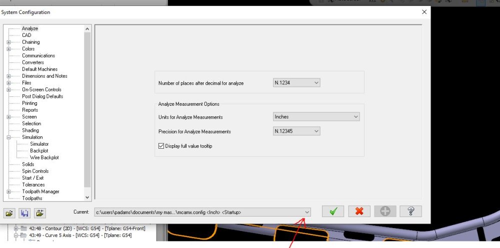
So I have always ran the model through model prep, removed history, etc than hit the file drop down , configuration and then switch mastercam from imperial to metric. It will ask if you want to scale the model answer is yes, Done. Usually I have the reverse work flow to turn metric models into Imperial though. In that case I open a new Mcam file switch to metric via same process, then import my metric model, model prep, switch to imperial, Scale Model, Yes, Done
It is important to have Mastercam in the correct metric or imperial configuration before importing any model, or things get weird. If its a metric model start in metric mode, if Imperial start in imperial mode. I'm sure their are many ways, but this works 100 percent of the time for me
-
1
-
-
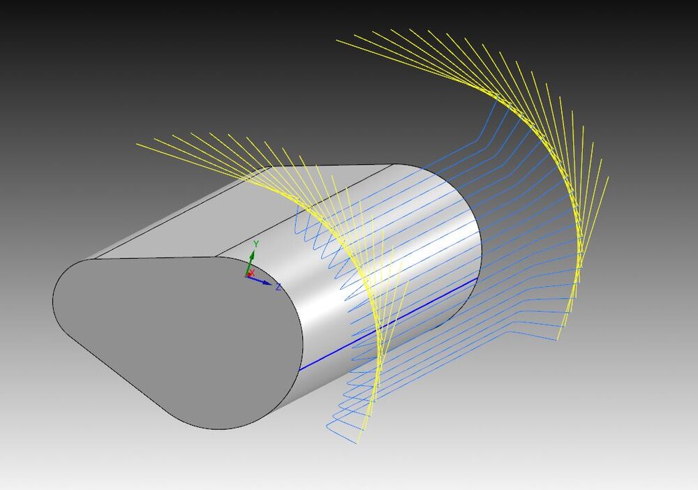
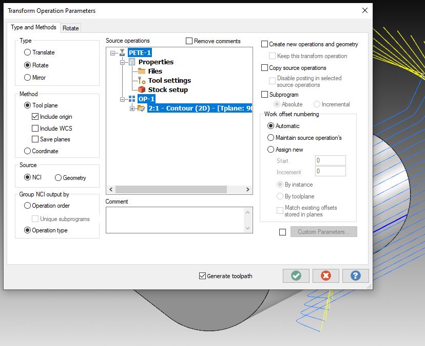
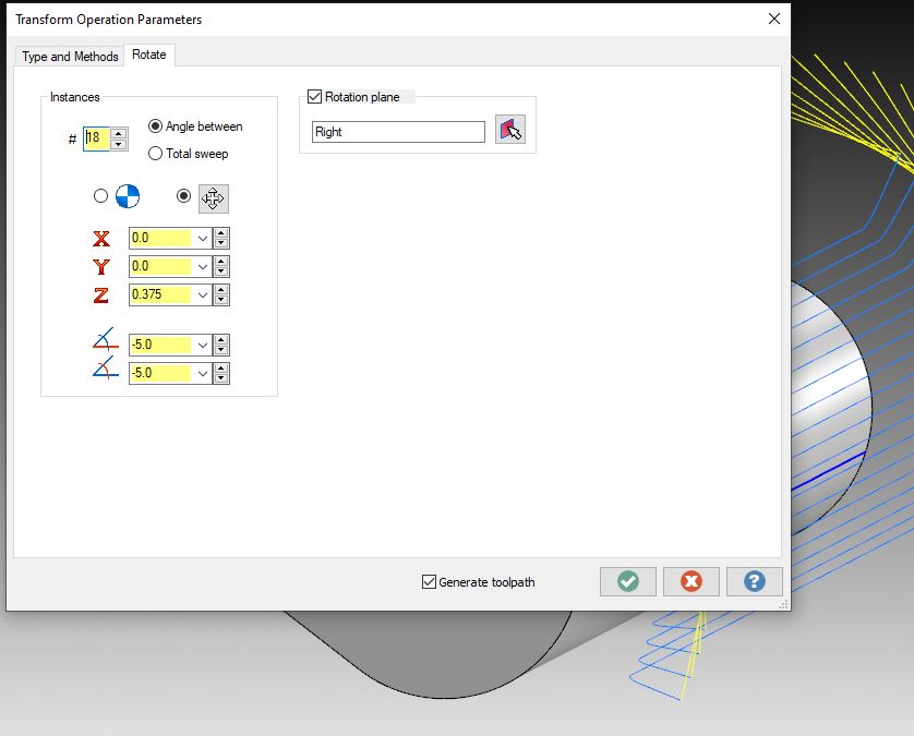
Super old school option.... Use a Contour, then translate/rotate the contour around the radius
-
2
-
-
35 minutes ago, Colin Gilchrist said:
Yo Pete!
No wrong way to machine a part, given your constraints. If your company is willing to invest in the options on the machine, then there are certainly newer options for making your life easier, all it takes is making the investment in a proper Post Processor, and purchasing the functions on the Control. But it does also take consistent practice in calibrating the Probing System itself, then going through and calibrating the COR (Machine Rotary Zero Point) Values.
WSEC is a God Send for machining Castings! If you are doing a bunch of that work, it may also be worth investing in Verisurf, so you can make measurements of the Castings "on the machine", and feed that measurement data back into the Verisurf model for a "best fit". This can be used to adjust your "main work offset" location on the part, to be able to "fit the features within the as-cast material". Used in combination with WSEC, this can not only make the setup of these complex parts "easy", it can help you to rescue castings where they are on the edge of not being workable by "best fitting" the finished part surface locations to the casting, and then correcting for the misalignments on the machine using the WSEC functionality.
Hey Colin, Merry Christmas my man, Definitely an ezier way, but you know me love beating my head against the wall. We do more castings as of late, So I am becoming better with everyone. I try to get them Qualified and straight into a 5 axis where I have the functionality. We are using vericut, Camplete and anything else we have to. We even got a 3D scanner, to make a raw casting STL. All of that and they are still my least favorite thing in the world. Lol
-
1
-
-
cant wait to get into this thread over break, looks like a lot of good info. I have always taken the simple approach. If I have rotations going in my Horizontals, I program from COR, set matercam up with my planes associative to a point, Go back the machine do some measuring and move my point to make up for any fixturing error. It sucks but I have always been able to get within a thou. any thing tighter I'll just set up a different work offset. If you have accurate models of your tombstones, or pallets in your case, you can get it pretty good. As for castings, God I hate castings!!! But I try to fixture to datum target points and usually don't need to shift after the initial set up.
All of that just to say I have been doing it wrong.. lol I Just wish our horizontals had dynamic work offsets, or Work shift error enabled, probe and go would be a God Send!-
2
-
-
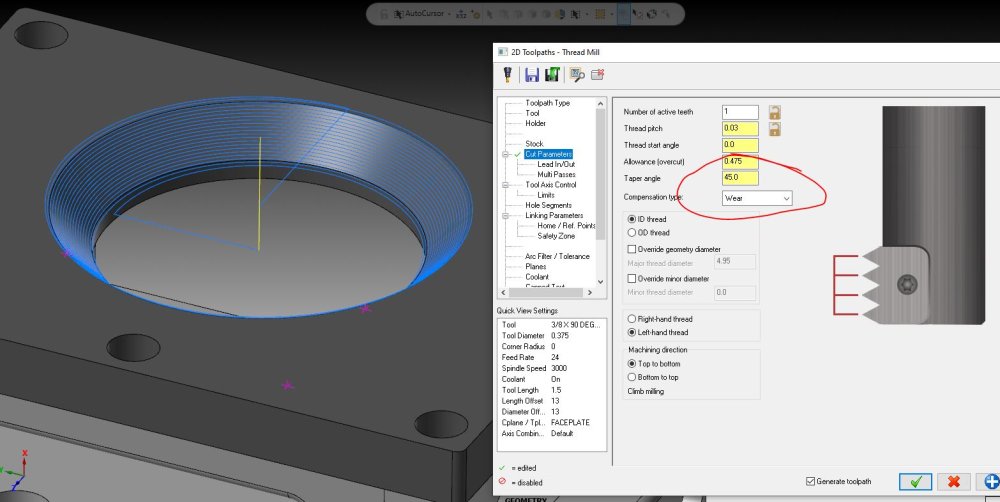
thread mill, you can use a small chamfer mill and taper angle, kind fun to play with. I too was bored once. lol
-
1
-
2
-
-
funny, I have been holding onto that Library since I don't even remember when, but like you I have had very few uses for it. But I no doubt will need it someday and I apricate the work that went into making it.
-
1
-
-
48 minutes ago, SlaveCam said:
They can call me a dinosaur if they want. If I have hundreds of operations based on wireframe based on a solid, and then I get a new revision of the solid (which is often), I have total control over the rechaining process. Is there a magic button that will rechain everything if everything was done with solid chaining only?
EXACTLY!!! I have tried a model based program, and then tried to incorporate a changed version through the change recognition inside the info tab, mind you this was an experiment with a very simple model maybe 15 toolpaths just to see how to use the change recognition option and OMG did I almost loose my mind. Sounded like a great idea to learn something new until I had several hours into trying to figure it out with less then optimal results... Never again
-
Im so glad to know I'm not alone in my decision to still use wireframe. I was afraid to tell people because I thought they would call me a Dinosaur
-
1
-
-
I have seen random arrow changing direction since 2021, or at least that's when I think they changed drilling. But fortunately for my machines we use Vericut, and or Camplete. Ive actually started to venture away from using solids to generate toolpaths, Which is sad because I truly love the simplicity of it. But every time I attach a path to the model, If I modify something on the model everything attached blows up, and models need to have history removed then regenerated in the solids tree, before I can regenerate toolpaths, Sometimes you can not save because of a dirty model, and then you have to do all the above mentioned. This sucks especially as I'm heading out the door at the end of a day.
-
1
-
-
YUP RANDOM FILE GROWING WITH NO CHANCE OF SHRINKING THEM BEEN GOING ON WITH US SINCE 2021. Many threads on the Mastercam form about it.
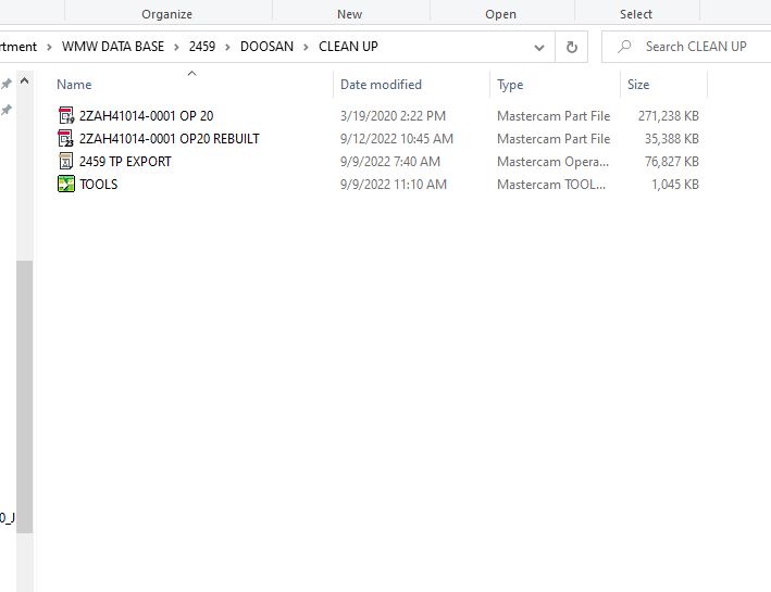
My work around is if I see it growing I save all solids I need as STP then open a new Mastercam file import STP models and start over! If you allready have toolpaths you can export them then import to new file, Seriously a real PITA!!!!
-
1
-
-
I am very limited on my knowledge of Macros, but have found some success over the years. Nothing for nothing in order for my macros to be able to use Goto lines and things that make them jump around they have to be saved on the machines Memory. Thats on Our Mori's with a Fanuc Control. I wasted alot of time testing in MDI and trying to write into programs that ran on DNC just to finally cave and call the Mori apps guy, He told me that I needed to save the macro into the memory and then call them from the program. Kind of how the renshaw macros work. So I tried it and now I seem to have better luck with my macros functioning as expected. This might not apply to you or anyone else but works for me.
-
28 minutes ago, Aaron Eberhard said:
I'm totally biased, but I'm agreeing with Ron..
The 5 axis toolpaths make this stuff so much easier, I wouldn't even mess with the old skool stuff (sorry Pete! :)).
I probably would these days too. but in my defense the one I did was 40 inch's long and the fastest way to get material out was a 2 inch shell mill and a 6 inch saw. Back then I wasnt to hip on using 5 axis paths like triangular mesh locked in 3 or 4 axis, these days I would love a part like that to show up.
-
1
-
-
I have done pylons like this before, I would not even hesitate to go with saw style cutters and old school toolpaths like Surface finish Contour. I think the biggest issue I see are the drilled holes at 90 deg. One of the ones we did was to big to even fit in the 5 axis, We had to stand them on their side and use a horizontal with an anglehead. Bottom line you are gonna want to dig out as much material as you can how ever you can and then (pro tip) let it rest and requalify before adding features of tolerance. This thing is going to warp... Have fun, these are the kinds of projects that you are going to learn alot
-
Maybe something is your Misc Values?
-
Update, Test part back from inspection. I am doing something wrong in the errors page for sure... My holes were shifted + 0.028 in my X direction. Every thing else I cut seemed right... Manager loosing patience, sad because I am this close to making a life changing thing happen in our set up and they want to shut me down when I'm 0.028 from the finish line. Lol
Im gonna give it one last go in the AM before everyone gets there. So any last minute suggestions are appreciated. I have my G54 set to the theoretical perfect point of Origin (which is where I am programed from in mastercam) I calculated that from the Standard G54 point kept on the control for COR) I am trying to figure out the best way to set the errors. What I am doing is setting the B axis orientation to get my part straight, then probing the center of the part to get my X while the part is in its new B location. I am using G58 to store the values. Then basically subtracting the location of my G54 from G58 to update my error Values. In todays case that was b-.101 and x .0469 and a z of -.0544. Am I doing this wrong? Any last minute help super appreciated


Smallest clearance 90° Right Angle Head?
in Industrial Forum
Posted
Also take a look at the product offering from Benz. I bought one a few years ago and its a nice piece. Their slim wgx-s might fit the bill but I don't speak MM.. lol
https://www.benztooling.com/en-us/metal/products/machining-center/angle-heads
Also as a side note I hate right angle head work... lol talk about PITA....