squirrel_41
-
Posts
25 -
Joined
-
Last visited
Content Type
Profiles
Forums
Downloads
Store
eMastercam Wiki
Blogs
Gallery
Events
Everything posted by squirrel_41
-
OKay thanks for that I will give it a try
-
Hi all I have tried many times to use map.dll I select the surface to map then the surface to map to but nothing happens even watching the part count in layers does not increase. Can anyone shed some light as to what I am doing wrong I have mastercam 2017 Cheer's
-
Okay that worked great I just had to make a small mod to the curve if you look from the top it did not match the original 2d drawing but it was just a matter of moving the front cut profile to the left 0.15mm so the profile intersected the first edge curve then cut the solid with the new profile and create a new edge curve. again thank you very much I have learnt so much more just from you'r short very well done video Mud Guard-V2.mcam
-
Wow I would not have tried that thank you very much . I did make a surface and a solid along the same face as you did but that's as far as I got I have downloaded your video and I am now going to try your method it looks great , again thank you very much.
-
Hi every one hope you are all well its been a long time since I posted here but I need some help so thanks in advance. I am trying to reconstruct a solid from the supplied 2d drawing I can get it very close but it is not correct. Basically it is a mudguard laser cut from 3mm plywood it has slots cut in it to allow it to be wrapped around the corners. I am only working on 1/2 the guard as the other 3 parts will just be mirrored. The problem is with the side that has the curve on when I cut the solid with the 2d profile the faces are not at right angles to each other like they would be if laser cut. I have tried for days and I cannot find a solution. I am attaching a cut down version 2017 mcam file. Cheer's Mud Guard.mcam
-
Thanks for I managed to get it to post what I wanted it to . But I did play with the toolpath editor and I added M10 as canned text just to see If it would be output in the G-Code I tried before with and after however it never posted to the G-Code it seems the toolpath editor may be specific to the Post cheers
-
Hi all I'm trying to modify the Generic Fanuc 5X Mill.pst that I have for a 5 axis welder that I have made I only need one small change to the output code but I have failed . N106 G0 M9 G54 G90 X-12.991 Y287.903 B37.073 A-107.921 S3500 M3 N108 G43 H0 Z-70.649 N110 G1 Z-170.649 A-107.922 F450. N112 X-30.32 Y213.368 (I need this line to have an m8) N114 G0 M9 Z-70.649 N116 M5 N118 m9 G28 I'm using m8 -m9 to turn on off the wire feeder and the problem is if the z is high it will feed down at G1 rate and of course the wire will be feeding . Can any help me thanks.
-
Hi guys I know this is probably a dumb question but can somebody tell me what keys to press to select the last selected geometry
-
mastercam 9.1 w/ GRBL
squirrel_41 replied to ch3no2freak's topic in Post Processor Development Forum
I just modded the Generic fanuc post to work with GBRL if you want a copy -
Hi Collin I appreciate the response The A axis is parallel to X axis C axis which I have renamed to B axis rotates about Z and is unlimited My machine it set up the same as 5_5AXGEN_VMVTTAB in the simulator The 'A' tilt access can rotate -+120 I had already done all as you suggested but the improvement was not great ? However I have since redone all the above checks and I am now happy with the results it seems I may have been a bit sloppy with my tests the biggest improvement was from using the center point of the ball rotating on the c axis as the rotation center. This machine is at best able to machine to 0.1mm in 5 axis I can get to about .05mm in 2d Now as for saxisx saxisy it seems only saxisy and saxisz has any effect on the code using mtype = 0 , I have tested this using 2d and 5axis toolpaths If I use mtype = 1 I get really strange results with mtype = 2 the results are more predictable but now saxisy has no effect but saxisx does so it seems if i need to use saxisx I will need to reconfigure and adjust below rotaxis1$ = vecy #Zero yx works here for the four tool plane directions using mtype = 0 rotdir1$ = vecx #Direction This is the A Axis change vecy to -vecy to change the axis direction #Secondary axis angle description (in machine base terms) #With nutating (mtype 3-5) the nutating axis and this plane normal #are aligned to calculate the secondary angle rotaxis2$ = vecz #Zero zy works here for non nutating axis the four tool plane directions xz works for nutrating axis rotdir2$ = vecy #Direction #this flips the Y axis direction but also flips the B Axis Direction -vecy only seems to work with m type 0 #Machine base matrix (Base matrix to map positions into) matb1$ : 1 # was 1 Make X axis neg matb2$ : 0 matb3$ : 0 matb4$ : 0 matb5$ : 1 # was 1 -1 make B axis flip 180 matb6$ : 0 matb7$ : 0 matb8$ : 0 matb9$ : 1 # was 1 -1 changes y sign but wrong value I have tried many combo's using Matrix base to reconfigure to use mtype = 2 but as yet have not got it to produce the correct code I will keep working on so I can use saxisx and perhaps saxisy together So to cut a long story short it would appear that the bulk of my problems come from a incorrect rotation center Thanks again Collin.
-
Mastercam X7 Mach3 Home made mill router can machine steel Yaskawa AC Servos Retired Mechanic Hi Guys I am in need of some help I have made a 5 Axis attachment for my machine and I have been trying to fix an alignment problem on Axis rotations This is a Table Table using the Generic Fanuc 5X Mill post non-nutating This is a simple cube first operation machine a step contour Top Top Top second operation machine side faces Top Front Front Transform rotate 90 All operations perform as expected the top contour is stepped in and down .5mm so I can check the Alignment after the side faces are machined now looking at the part from the top the left and right side faces are off center to the left X- b y about .25mm I have probed a ball on the C axis table to check the alignment and done the same with A axis rotated 90 degrees I have used the intersection of the of the probe points for the rotation center I have done this at least a dozen times with no improvement there is obviously an alignment problem but I cannot work it out I have thought about it a lot and I cannot point the finger at the axis that is causing the problem . This a a home made unit and I not looking for micron accuracy I am just trying to get my head around what axis is creating the error saxisx :0 #The axis offset direction? using mtype 0 does NOT effect the code using mtype 1 or more does effect the code saxisy : 0 #The axis offset direction? using mtype 0 a value here DOES effect the code saxisz : -9.023 #The axis offset direction? I would really appreciate it if some one could point me in the right direction Thanks.
-
I have been suffering this problem as well and i have tracked it down to the machine simulator select a level with a known amount on entities in it run a machine simulator and the count will go up depending the machine you select some increase the count by 2 some others by 5 or more do a level report showing all items , the active level when you started the machine simulator will 2+ "Copious Data" as yet I have not been able to remove this data. This is a real pain in the but and has been sending me nuts trying to find it so if you run the simulator use a level with Geometry on it so can just delete the level
-
Home / Ref. Points Not consistently posting
squirrel_41 replied to N.Skinner's topic in Industrial Forum
Hi I had the same problem what i did to fix it was to use the update post utility and it fixed it. UPDATEPOST.DLL -
Okay I might try that I have asked this question before and had no replies ? who is QC
-
I appreciate the understanding of tabs and the need to keep them small so they can be broken or cut I also can work out methods to accomplish said task by using extra geometry, but this can be a real pain especially when you are developing a component and the contour is constantly changing from version to version. The tab function has the option to set the tabs to partial or FULL if you set the full option you would definitely need a step depth setting. It seems strange that all functions in the separate operation can be changed and work except for the depth step setting.
-
Hi guys I have a need to cut off contour tabs as a separate operation these tabs are large and need to cut with a depth step There seems to be no way to set a depth step although the function is available , setting a depth step make no difference changing other functions like top of stock and max depth and lead in lead out all work as expected but not depth step any idea's thanks.
-
Pity View sheet does not remember mask
-
I had the same problem but the fix is to go to settings configurations scroll down to verify settings un check "Center On Axis" this will fix it.
-
Okay I applied the 3gb boot switch option on my 32 bit system and woopee it solved my problems This is the method I used To enable the 3GB switch: Right-click on the Command Prompt icon in the Accessories program group of the Start menu. Click Run as Administrator. At the command prompt, enter: bcdedit /set IncreaseUserVa 3072 Restart the computer. To disable the 3GB switch: Right-click on the Command Prompt icon in the Accessories program group of the Start menu. Click Run as Administrator. At the command prompt, enter: bcdedit /deletevalue IncreaseUserVa Restart the computer.
-
Saving a useable STL file out of X7 Verify
squirrel_41 replied to CamMan1's topic in Industrial Forum
Machine Simulation Transform rotate would not work so I tried this and it worked perfectly Mastercam X7 what I did was transform rotate Then save the NCI then Import the NCI Then simulate the imported NCI it works correctly If anybody wants a copy of this file I will email it to you.
-
Saving a useable STL file out of X7 Verify
squirrel_41 replied to CamMan1's topic in Industrial Forum
Well thanks very much for that I would say you have it in a nutshell. I can get the part to verify using very touchy and precise entry and exit lead in outs . But if you make a slight change to the tool depth or step over in any tool path it all goes out the back door. In any case you are dead right about the location of the Z being relative to the tool plane and therefore the Z retract is a completely unknown. These paths are transform rotate. I also do not understand why there is no home location value for rotary axis. In the tool linking if you enable start form home position and return to home position it goes bad the XYZA can end up any where and this is also reflected in the G-Code and cost me many broken end mills and destroyed part. So is it safe to say that if it verifies correctly in Machine simulation this is what I will get when I actually machine the part ?. I am so glad that you have clarified this for me Its a pity this is not stated some where in the help files This has been a nightmare for me for many years ,it is only with the advent of machine simulation that I have been able to make some sense out of it. I really thought I was going nuts because I have been chasing a answer to this for so long. Because of this problem I have tried many other CAM software and it is my personal opinion that with all it pitfalls Mastercam is still the best of the bunch if I was in business it would be my choice. Thanks very much Guys I think I can finally put this to rest Regards Bob Andrews. -
Saving a useable STL file out of X7 Verify
squirrel_41 replied to CamMan1's topic in Industrial Forum
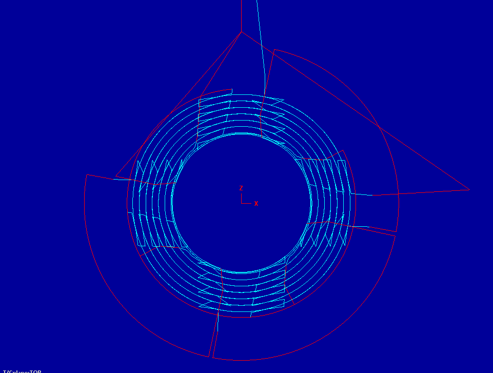
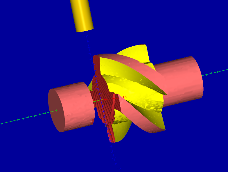
This is a image of the Backplot tool path it clearly shows no path through the center of rotation and machine simulates correctly yet the same tool path in Verify cut straight through the part . This has been sending me nuts for years and I have no faith in the verify. I must be be doing something wrong.

-
Saving a useable STL file out of X7 Verify
squirrel_41 replied to CamMan1's topic in Industrial Forum
I Attached the file as is but I don't see it in the replied post ?. -
Saving a useable STL file out of X7 Verify
squirrel_41 replied to CamMan1's topic in Industrial Forum
Do I attach the file as is or zip it P.s I still have not resolved this. Regards Bob -
Saving a useable STL file out of X7 Verify
squirrel_41 replied to CamMan1's topic in Industrial Forum
Hi Guys I am a retired mechanic and have been playing with mastercam for quite a few years at home on my home built machine with Mach3. I don't work this is just a hobby for me. My problem has persisted with every version of Mastercam I have tried including X7. I have a 4 Axis tool path that machines perfectly I even built my machine Simulator exactly as my machine In the machine simulator the backplot and verify work correctly. However in normal verify the part gets hacked to pieces I am as stubborn as a mule and have been trying to solve this same problem with the same part for about 3 years " I would be backrupt if i was doing it for a living" I have exhausted every avenue I can think off I have been able to get it work but I have to put in ridiculous retracts and moves I don't understand why it machines correctly and I can make a correct stock model but gets hacked up in backplot. Is it possible for one of you very knowledgeable guys to take a look at so I can move on with my life. I'm sorry if this is the wrong place to post this I rarely post any where. Edit I think i have finally solved my problems 3ax ver 5ax engine i read in a previous post. So I think this is solved for now .