.jpg.1d0c9069edb5ce000980cbe1b76f0865.jpg)
CEMENTHEAD
-
Posts
359 -
Joined
-
Last visited
-
Days Won
4
Content Type
Profiles
Forums
Downloads
Store
eMastercam Wiki
Blogs
Gallery
Events
Everything posted by CEMENTHEAD
-
.thumb.jpg.15afa8dbfcde0167893a4a297d335e0b.jpg)
Need Help- missing feed rate on 4axis motion
CEMENTHEAD replied to Machiner32's topic in Industrial Forum
Pretty sure your HAAS has a parameter to set the Diameter of your rotary, I'd check that. -
although I do miss the YELLOW TEXT menu to the left.

-
looks like a graphics card issue. tbh also looks like an X version. which I'm pretty sure they won't support anymore.
-

-
use the .SET file version. The active reports are sooo painful. shiny but still painful.
-
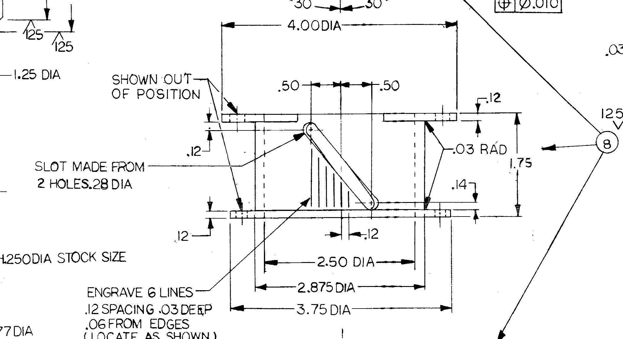
I have the assy dwg, a pin on a shaft follows the slot as an indicator. I know Its a xxxxty way to dimension it. should be a section view with angles. (dwg is from 1985)
-
That was my first attempt, I did a .28 square normal to the angle and sweep thru the cylinder (hoping to fillet the corners after) but it yellow box errored out.
-
projected the points onto the cylinder, unrolled at Ø2.875, Create 2 lines tangent, -- ReRoll The machining part is done, I was just banging my head on the model. I could have sworn I've done this before. like I said I just hit the wall on this.

-
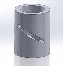
I could use some ideas to model this feature. Can't seem to figure this one out. I can unroll geometry to machine it. The programming part is done (axis sub), But modeling it I have hit the wall. I attached a mcam 2021 file of the problem area. angle slot on dia.mcam
-
ya ya .. I didn't see MM always thinking Imperial...
-
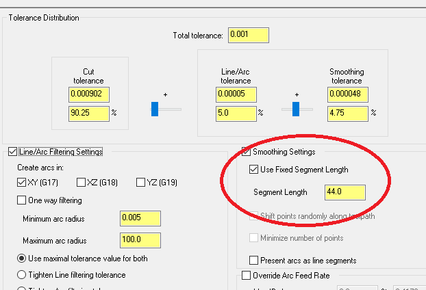
¿ seems backwards here, what you have circled will break all your lines and arcs to .075 long segments. yet your total tol above seems real high at .025 and will give you an extremely faceted surface. My default for smooth finish is total tol = .0005 and what you have circled I use a large number like 22.0 (I don't want to break circles, slplines or lines). I also check the "line/arc" box with XY on. (smallers up the code)
-
I don't know if you have this on or not, but having "outline shaded" on can cause that to happen on very large models. try using "shaded".
-
Agreed wit JP, we do similar parts, We 5X swarf the walls and surface the floor and rads on the top. (Tapered pintles is where all the fun is at)
-
ditto SOCCERBALL.mcam
-
That's what I normally do as well.
-
I always copy over our old posts into the new version, backing them up as well. then update them. (comparing the output to the previous version. Always side by side installs! I never just update the old ones. you could be left out in the cold with no running posts.
-
IMHO I would ramp/circle mill the holes thru, much less pressure and waaay less of a burr.
-
model prep, modify feature, have create body selected.
-
I also use Fixed segment length. when using dynamic paths and cutting splines sometimes you can get a series of breaks in a single axis move. this eliminates them quite well. (WITHOUT FIXED SEGMENT LENGTH) N1G17G98G40G49G80G90 N2G0X0.Y7. N3T1M6 N4S1000M3 N5G0G90G54X-4.2745Y2.4416B0. N6G43H1Z4. N7M08 N8Y2.4415Z.1 N9G1Y2.4416Z0.F10. N10G41D1X-4.2245 N11G2X-3.1005Y2.6916I.5898J0. N12G1X-2.2949 N13X-1.2949 N14X-.2949 N15X.3784 N16X1.3784 N17X2.3784 N18X3.3784 N19X3.8539 N20G2X5.0489Y2.4416I.5714J-.25 N21G1G40X5.0989 N22G0Y2.4415Z4. N23Y2.4416 N24M09 N25G0G28G53G49Z0.M19 N26G90X0.Y7. N27M01 (WITH FIXED SEGMENT LENGTH AT 44.00) N28G17G98G40G49G80G90 N29T1M6 N30S1000M3 N31G0G90G54X-4.2745Y2.4416B0. N32G43H1Z4. N33M08 N34Y2.4415Z.1 N35G1Y2.4416Z0.F10. N36G41D1X-4.2245 N37G2X-3.1005Y2.6916I.5898J0. N38G1X3.8539 N39G2X5.0489Y2.4416I.5714J-.25 N40G1G40X5.0989 N41G0Y2.4415Z4. N42Y2.4416 N43M09 N44G0G28G53G49Z0.M19 N45G90X0.Y7. N46M30 %
-
I had this problem earlier this week (not as bad tho) I fixed it with a small line tangent at the feed in and out.
-
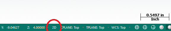
I'm sure were all aware of how offsetting a line reacts whether your are in 2D or 3D. ( 3D keeps the Z of the existing line while 2D uses the Value in the Z field ), this also worked the same way creating lines using parallel or perpendicular. That being said. in 2021 "automatically determine Z depth" is available on create line endpoints, and even line perpendicular BUT not on Line Parallel. Create line Parallel no longer changes depths between 3D or 2D. Seems stuck in 2D mode.
-
or... Alt+Space bar
-
Also make sure the cable is not looped up or crossing any power cables either . Sometimes people get lazy running cable and loop up the excess at the end or loop it up with other cables. It forces data to pass near the same point multiple times causing a small magnetic field which can cause data corruption/loss.
-
We tape cloth over all the ways, and run dry with the vacuum. I also find Cobalt is the best as you are going to have to a bit of regrinding.
-
our IT guy disabled the AV and it seems to be fine as a work around. But no AV will have to be addressed.