


powerfulp
-
Posts
99 -
Joined
-
Last visited
Recent Profile Visitors
1,074 profile views


powerfulp's Achievements
")
Newbie (1/14)
2
Reputation
-
Curve All Edges flattens wireframe geometry
powerfulp replied to powerfulp's topic in Industrial Forum
Hello Leon82, Thank you, kind sir! As you know, this worked! I can now select what I need to. I don't remember switching to 2D, but nonetheless ... Thanks. Regards, Paul -
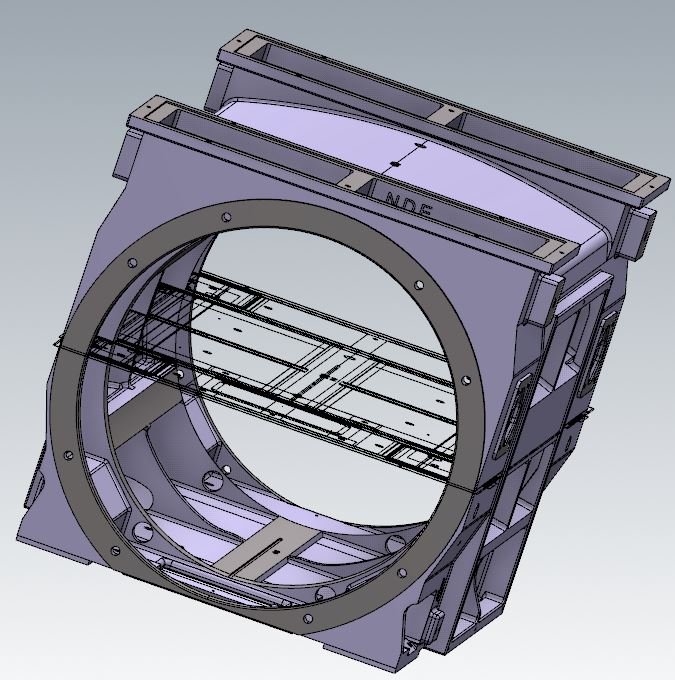
Hello - I am running Mastercam 2018. I imported a model, it was an iges file. I could not select on any edges when I went to Analyze Distance mode, so I selected the entire model and used Curve All Edges. That flattened out all the wireframe geometry (which was weird - see attachment), and I was still unable to select anything on the model when in the "Analyze Distance" mode. When not in any mode, I can select surfaces on the model, but not edges or centerlines of holes, or anything else. Did I accidentally activate something I shouldn't have? This flat wireframe geometry thing after Curve All Edges has happened on all my models as of late. And to make things more confusing, I was still able to select on the edges after I did Curve All Edges every time the wireframe geometry was flattened out, like in the attached image, before now. Any help is appreciated. Thanks. Regards, Paul
-
Thanks for the replies! I turned off the Use Group and Result color in Xform in Configuration/Colors and that worked. Thanks again.
-
Hello - The weirdest thing is happening when I move (translate) a model of a part: After the move and after I clear colors, the model color changes to the color of what my Solid color selection is (I don't want it to change colors at all). This was an .iges file. Then I merged another model (the machine table) into this one. I then changed the color of the table. Now when I move the part, either via the translate command or moving it using the Dynamic Xform method, the part color changes to the color I changed the table to after the move. The model had all the machined surfaces a different color than the casting surfaces, which I want to keep, but instead, the entire model color is changed as mentioned above. Why would this be happening and more importantly, is there anything I can do to keep the models colors intact? If not, then I have to individually change the color of each surface, which I would be willing to do, however, when I try to select an individual surface to do these color changes, it will only select the entire model, it won't just select an individual surface. This is odd to me as well, since normally when I import an .iges file I have no problem selecting individual surfaces. Is there a way I can select and change the color of an individual surface in this instance? Thanks for any help.
-
Hello - When I made solid models and say I have to add a chamfer, there is always a line showing the original geometry I used to create the original entity. It makes the models look like crap, I think, because you have this extra line where you don't want anything to be anymore. Hopefully someone out here knows what I'm talking about. Is there a way to delete this without destroying your model? Or a way to hide them? When I go to delete them, a window pops up that says, " Some of the geometry selected is associated with a Toolpath, Solid or a Named View. Deleting this geometry will permanently alter those operations". Then gives me the option do "Delete all selected entities" (which messes-up the model - can't regenerate), or "Delete only non-associative entities", which, does nothing (that I see). Anyway to around this or is this just the way it is? Thanks for any help.
-
Hello and thanks for the replies. So what I ended up with for this (with some help), was: Oxxxx (Start of program) T1M6 #3001=0 (Initialize continuous millisecond timer) xxx (Runs the tool) xxx T2M6 #601=#3001 (Stores total time from M6 to M6, essentially, for T1) #606=#606+#3001 (Starts accumulated total time) #3001=0(resets timer) xxx (Runs tool) xxx T3M6 #602=#3001 (Stores total time from M6 to M6, this time T2) #606=#606+#3001(Accumulated total) #3001=0 etc. till the end of the program, then: #605=#3001 (Stores time for T5) #606=#606+#3001 (Accumulated) (Now, execute a DO Loop to move all the cycle times up one non-volatile variable at a time , then putting the most recent cycle time at the bottom) #1=1 WHILE [#1 LT 10] DO1 #[#607 + #1] = #[#607 + [#1+1]] #1 = #1+1 END1 #617=#606(Enters entire cycle time in #617 #606=0 #3001=0 M99 (Note: I wanted to skip a couple places for separation on the screen) If you wanted to, you could put the time it takes to load, unload a part by doing a #3001=#619 before the first tool change.
-
Hello - I know this is a Mastercam forum (& I use mastercam) but I know there are some smart folks here so I pose this question: I am trying to figure out how to write some macros in my g-code program that does the following regarding cycle times: 1 - Stores cycle time for each tool every time they are ran. But only keeps one record, the last one. 2 - Stores entire program cycle time. 3 - Stores the last ten program cycle times so they can be easily reviewed. Here is what I have figured-out thus far: The program has five tools and my machine has permanent common variables up to #699 so I thought it could go like this: #601 is for T1's cycle time #602 is for T2's cycle time #603 is for T3's cycle time #604 is for T4's cycle time #605 is for T5's cycle time #606 is for accumulative cycle time #607 thru #616 would store the last 10 cycle times. (This is on a Mazak Horizontal Machining Center with M-32 control) So to get and store cycle times for each tool and to get and record the entire cycle time, I would just do this: (First tool runs...) M6 (Dont' know if I should put the following before or after the tool change) #602=#3001 (using millisecond counter for getting the cycle time for this tool) #606=#606+#3001(Accumulated time) #3001=0 (Next tool runs) #603=#3001 #606=#606+#3001 #3001=0 (Last tool runs) << Same thing with the macro but #3001= happens before the shuttle, not after an M6>> (Part shuttles out, is changed, and cycle start is hit) M6 (beginning of program) #600=#3001 (tells you how long it took to switch parts and start up machine" #607=#606+#3001 (Stores entire cycle time in #607) #606=0 #3001=0 So I'm thinking I will have to do a conditional statement somewhere in the macro, with a counter, etc in order to get and store the next nine cycle times in variables #608-#616, but I can't figure out exactly how to write that. Can someone help me out with this? I'm pretty green when it comes to macro programming but I think it's awesome and want to learn more and more ways to do stuff with it. I'll continue working on it as I wait for a reply. Also had another quick question: Does the millisecond timer start over after like 60 seconds? I've hear that but then I heard that it goes on till power off or for 77.7 years... Any help is appreciated ... thanks.
-
Thanks everybody for the info. Chris, so the "new" tool manager is for X7? Not available for X6?
-
Is there a way to import specific tooling into your tool libraries for the milling side of things? Like in the turning area, you have specific tools from manufacturers that are in that library. For the milling, all I have are generic tools like 4.0" face mill, 1.0" end mill, etc. (I don't see any button mills, which is what I'm looking for at the moment.) I'm using X6 right now, I will be downloading X7 as soon as I get a new computer which is hopefully in the next week or so. I'll start here and see if anyone can help me. Thanks.
-
Hello, I have made a quick solid model and now I want to make a drawing from it. When I select either "Dimmed Wireframe" or "No Hidden Wireframe", they don't work. The drawing just displays the "Wireframe" version, which will not work for the drawing. Is this normal? Or how do I get these to work? Thanks for any help.
-
Change drilling depths within a drilling cycle in mastercam
powerfulp replied to powerfulp's topic in Industrial Forum
Here's what I did: I just did all the drilling at one B-axis position, then started another cycle with the same drill and rotated the T/C plane to where I was machining at the other B-axis position and this looks like it worked. I'm sure there are countless other (probably better) ways to do this, if anyone would like to share I would appreciate it. Thanks! -
Change drilling depths within a drilling cycle in mastercam
powerfulp replied to powerfulp's topic in Industrial Forum
Ok, Roger, I used what you suggested and it worked great for changing the Z-depths to different values for holes that go to different depths with the same diameter drill. Thanks. However, I still cant get it to use different R-planes for different holes. The R-planes AND the final Z-depths are different for each hole. I tried to select on each hole individually with Top of stock with Absolute selected and it just uses the last one I selected.... ALSO, I have another problem, I don't know if I should start another post for it, but it's kind of related. I am drilling on a horizontal machining center and using this same drill, I have to rotate the B-axis to B90 and drill a hole there. How on earth do I get the orientation correct to drill that hole at that angle along with drilling the other holes at B0? Thanks again for any help. -
Hello, How do you change drilling depths for certain holes in a drilling cycle in Mastercam? I know this is basic stuff, but I've been trying to figure it out long enough so I come here for help. I have a drill/counterbore cycle. I selected the holes to be drilled by "entities". Some drilled holes have different R-planes and final Z's. On my "linking parameters" screen, there is the Retract... Top of stock.. and Depth... I can enter, but what if they are different hole-to-hole? Thanks for any help.
-
how do you post to use G19 (YZ plane for circular interpolation)
powerfulp replied to powerfulp's topic in Industrial Forum
So you're saying Mastercam will never post an arc using G19 in Y & Z if moving in the X-axis simultaneously? I would have never thunk it. I figured it would be something like helical interpolation. Well, since I couldn't get Mastercam to post it, I programmed it manually and this is some of the code that worked (cut geometry correctly/no arc error alarms): N15960 G0G90G54X-11.6440Y6.4000S495M3 N15970 W-2.0000 N15980 G43Z2.0060H129 N15990 G19 N16000 G1X-11.6440Y2.8365F30.0 N16010 G2X-11.0862Y1.4899Z2.2434J0.0000K3.9370F15.0 N16020 G1X-10.6180Y.3608Z2.6544 N16030 G3X-10.0602Y-.9858Z2.8918J-1.3466K-3.6996 N16040 G1X-9.8000Y-1.4000Z2.9000 N16050 G0Z5.0000 And yeah, I'm sure I have some things setup goofy, I don't have much experience with Mastercam. We've had it for over a year but I've probably worked on it a total of a week or two. I'm planning on working on it much more in the near future.... Anyway, thanks for the info. -
how do you post to use G19 (YZ plane for circular interpolation)
powerfulp replied to powerfulp's topic in Industrial Forum
nobody interested in this one anymore? or do you need more info? Or ?? thanks for any help
