dannysdad
-
Posts
78 -
Joined
-
Last visited
dannysdad's Achievements
")


-
gcode "to move geometry inside the Level Manger you right click a level and select cut or copy right click a new level and select copy or paste all the geometry in the donor level will be copied or moved" Yeah, that isn't working. The "paste" remains grayed out. ******* jlw "Or select geo, right click on work area, click on level icon on the right, when it pops up click copy radio button, pick level, green check " Yes, this worked! Thanks!
-
Good Morning. Just starting working with 2017 this week, (upgraded from X6) and what a shock! I do not know where all of my tools are ....but I am slowing learning. This is something I cannot figure out: how do I move geometry from level to level? I have right-clicked in the levels manager and used the "cut entities" process. I then pick my entities (at this point I would hit "enter" in X6 and then move my selection) but then what do I do? "Enter" doesn't work and there is no green check either. Note: I have the feeling that this will not be my last roadblock. Thanks!!
-
Update for anyone interested. Using Internet Explorer (not Chrome or Firefox): -Enter Vault -Search for file -Results will populate a list -Click on wanted file -General properties screen will emerge -Click on file -Popup screen will ask to either open or save file -Click dropdown on save option -Select "Save as" (I created a new folder on my desktop for these saved files) -Save file to selected folder -This gives user a path/destination for merging files Thanks for all of the help! Cheers! -
-
Watcher, Thank you very much for your very informative, knowledgeable and detailed response. I am now waiting for my Autodesk/Inventor guy to come in and explain it all to me!
-
Hello Folks, My company has decided to move all .dwg files from a local drive unto Autodesk Vault. In the past whenever I wanted to file/merge a part file into Mastercam (X6), I would specify the local drive (in my case it was L Drive) and then follow the engineering tree until I found that file, click on file and then Mastercam would import the file. But now all of our part files are on some cloud someplace that I cannot seem to access through Mastercam. I have access through the web and I can view/print files through my DWGTrueView but i cannot find the path for merge. Any advice? Thanks and Happy Cinco de Mayo!
-
Ok man, I have got it to where I believe it will arc off with a nice blend and without gouging. Thanks a bunch. I was thinking that there was a way to ramp off, I just looked right pass the possibility to arc off.
-
Hey djstedman, Thanks for the input...but you lost me. ============== Let us start here: "just figure out how much you want you actual radius for the center of the tool to travel.. lets say .03 then in the percentage box add 50 percent" Ok..what percentage box? Entry length? Or Exit length? ============ Moving on.. "figure the actual distance you want the cutter to move in a straight line and add 50% of the cutter" Is this where the cutter is actually moving off the part? At this time is the cutter moving perpindiular to the toolpath? If so, I only have about .370" to move in that direction, doesnt seem like a whole lot of room to ramp. That is why I do not want to ramp off perpindicular to the toolpath but instead on the same vector as the toolpath. I was hoping MC could do this. I will just have to manually enter these values. Or write a macro. Thanks
-
We bought the Mazak HSN 6000 II last year and purchased MC with it to produce the programming. We had issues with “wear”, anytime we loaded it into the machine it would throw an alarm. We had the Mazak guys in here and they could not figure out the problem, but when we used “control” on the same tool paths, we had no problem. Since then, I have used control. However, it makes no sense to me that I cannot control the path of the tool when I come off of the part using “control” and I can using “wear”.
-
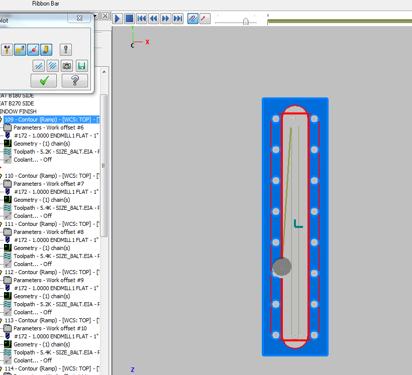
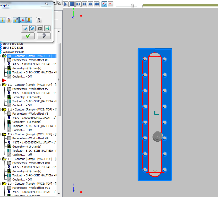
Hello friends, I am milling a 1.379”x12.688” slot with a .689 radius at both ends at .41” depth. I am using the “contour, ramp” tool path utilizing a 3° ramp. I am using a Seco 1” square-shouldered, indexable, flat-bottomed endmill. I was wondering, how do I “ramp off” of the slot WITHOUT gouging the part? If I try a tangent exit, the tool path dives left into the part (screen capture 2). If I try a perpendicular exit, the tool path dives right into the part (screen capture 1). Is there a way to ramp out on the same line as the tool path is going without going left or right? At present, when the tool leaves the cut, it is leaving a ripple in the finish which is marginally unacceptable. BTW, my tool compensation is set on “control”. Thanks, Chris
-
Hey kdgrills, I tried that slot mill toolpath when I first got MC5. From what I recall, I had so many problems with it that I never tried using it again. It has been a while, so I cannot remember what was wrong.
-
Rotary Ninja, Thanks for the input...maybe I did get lucky. But yes, comp set for "computer" and lead-in/off is off.
-
boatdudeguy, didnt work...but thanks. gcode...good solution to the problem, it worked but I am still stumped as to why a process that worked before now does not work. Thanks
-
BTW...I am running X6
-
I have a family of parts that has a .625" width thru slot which I cut with a .625" insertable endmill. I set up my first slot which is 9.125" long and MC cut it in one pass...which is what I wanted. I exported the process to cut a different part with a 7.875" slot, same .625" width. No dice, I got a "Cutter compensation not sucessful" window and it would not process the cut. Same width, same tool...no changes were made with either. I have tried chaining it differently and still nothing. So I changed the dimension of the slot to .62501", and it worked...only it cut down the slot...then back up, two passes...I do NOT want two passes!! Investigation followed. I went back to the original part, which cuts in one pass, deleted the original geometry for the slot and re-drew the EXACT same dimensions. Using the same process, I re-chained the new, EXACT geometry and I got the "Cutter compensation not sucessful" window again. This was on the original, WORKING process with the exact but replaced geometry. I am completely stumped. Thanks in advance