


Hertz
-
Posts
352 -
Joined
-
Last visited
Recent Profile Visitors
1,248 profile views


Hertz's Achievements
")


-
Not too sure about this though as normal threading retracts fast, as normal.
-
After playing around with the cycle, it seemed that the switch from G32 to G00 had a split second delay, which was causing the groove. I changed the G00 to the next line in Z after retract and it works fine now. Only thing is that it retracts in inch/rev. A thread with an undercut should never experience this problem.
-
Ahh, yes, of course. Thank you. I knew it was something simple.
-
Good morning, It's been quite awhile since I have used a lathe toolpath from a solid model. I vaguely remember being able to apply a wireframe to the model to create a lathe toolpath but I can't remember how. I have a 3D solid model of a disc with a profile, but I need to put it on the lathe first. I took the model and did a dynamic transform to get the proper orientation, but now I don't have the geometry to apply a lathe toolpath.
-
This did it. Thank you very much. I didn't even realize I could do this. Appreciate it very much.
-
Good morning, I'm trying to do a 3D toolpath flowline but unfortunately the license we have has one surface/solid face at a time only. The toolpath I have is basically a large chamfer along 2 edges with a radius in the middle (technically 3 surfaces) so when I try to do a 3d toolpath, I get the error with the license. Is there a way to merge surfaces to make it as one to be able to use the toolpath? Or is there another way I can achieve when I want to do? I attached a screenshot of the toolpath I'm looking to do.

-
Good afternoon. Just wondering if any of you have a rule of thumb for scallop height and surface finish relation. Like I mean, if you make a toolpath for .001 scallop height vs one with .005, how much is surface finish sacrificed?
-
This was it. I feel like an idiot. I re drew the part and extruded a cut into the square with the proper depth and it worked. What I did originally was the square and the hole so it cut a hole right through, then I just extruded from the back. That's exactly what it did was create 2 models. Had I looked in my toolpath manager, I would have seen it. Thanks fellas.
-
It's not a through hole. I had no problem drawing the radius once converted to surfaces, but from the solid mode, it does it backwards. Might be how I drew the model? The hole was originally a through hole, but I extruded the make a c/bore. I'll upload a file shortly.
-
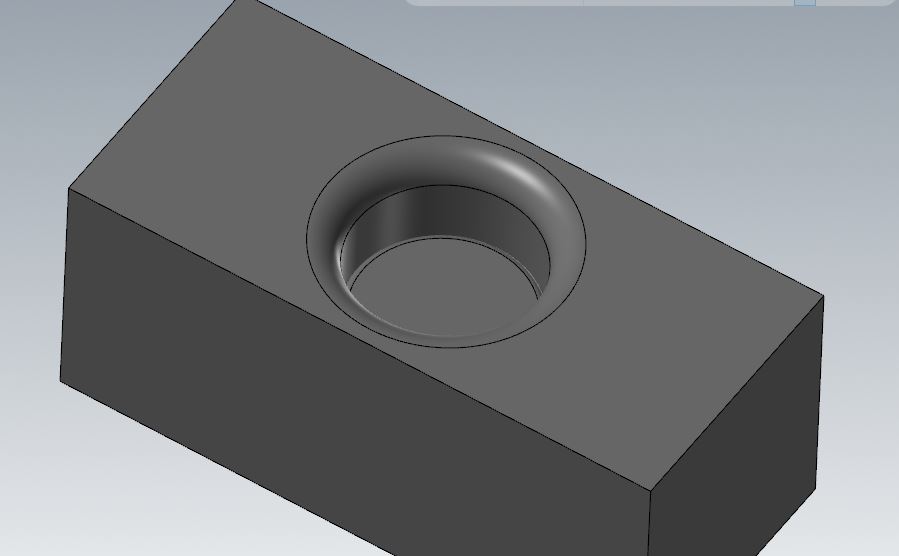
yes it is a c/bore. At the bottom of it, I'm trying to add a 1/4 radius. Doesn't matter what I select, it puts the fillet reversed.
-
Good morning, I'm trying to add a fillet in the bottom of this hole, and when I select constant fillet and the size, it works, except it goes reverse. The fillet goes down on the sides instead of up. Is there a way to reverse the direction of the fillet?

-
This worked for me. Thanks for the tip.
-
Yeah I noticed that as well. Unfortunately, can't get it to stop completely. This is very weird. I'm sure this wasn't an issue for me before as I've used this type of toolpath many times.
-
No. If you backplot the toolpath and watch the numbers, you will see extra z heights. I'm looking at it right now and the 2nd pass Z height goes across at Z.2441, then jumps to Z.2443, then moves in X, and then Z again to Z.2314, then comes across. It keeps doing this throughout the toolpath. I was expecting it to go across at Z.2441, then move in X, then down to Z.2314. I don't understand what the extra z move is for(.2443) Almost seems like it's retracting for clearance but only .0002 at a time.
-
Can anyone help me with why my toolpath is moving in Z height more than it should be? See attached test file. I am expecting the toolpath to just go back and forth with a Z and X movement after each pass, but it is adding extra micro z movements and it's causing the machine to slow right down to read it. My mill doesn't handle those moves very well so I'd like to have it not do it. I'm not sure how to stop it or why it's even doing it at all. test flowline.mcam

