sunderlandjoe
-
Posts
14 -
Joined
-
Last visited
Recent Profile Visitors
442 profile views


sunderlandjoe's Achievements
")


-
Bump still trying to fix this. @Colin Gilchrist were you ever able to find the post with a fixed acceleration distance? I'm trying to figure out how the post logic is working. What is wrong is it is not using the value entered in the "acceleration clearance" area when a Lead-in angle is present. Additionally I determined by second line Q value is wrong but I can't find where it does the math (thread depth/(Sqrt(number of passes)). This appears to be what the *thdfirst$ is but that has no visible logic attached to it that I can find so far.
-
New computer sending different g code
sunderlandjoe replied to sgizynski's topic in Post Processor Development Forum
Understood. I have a legitimate copy, I just stopped with the maintenance. -
New computer sending different g code
sunderlandjoe replied to sgizynski's topic in Post Processor Development Forum
For the uninitiated why does it matter that he's a first time poster? -
Bump, still a problem.
-
I would really appreciate that if so. Even just to compare and make the appropriate edits to my post.
-
I know how to do the math manually so I can change the value myself, i'm just trying to figure out how to fix my post so I don't have to do that. I tested the latest MPLMaster post from here and it still does it
-
Yes, but you can see in the above that it added .0608 to the start value but the R value didn't change accordingly.
-
So I've got a weird post issue. If I post out a G92 threading cycle the Z start point will match my acceleration distance as it should for example as .2. If I post it out in G76 the start point is .2 with a lead in angle of 0. but if I post it out with a lead in angle of anything other than zero it changes that Z acceleration distance but does not adjust the taper to suit. Any one have any insight into what is going on here and how I can fix it? Examples: With lead in angle at 30° G0 T0303 G97 S380 M03 G0 G54 X4.2333 Z.2608 M8 G76 P010030 Q0030 R0030 G76 X3.7683 Z-3.95 P1325 Q0271 R-.3458 F.25 M9 G28 U0. W0. M05 M30 With lead in angle at 0° G0 T0303 G97 S380 M03 G0 G54 X4.2333 Z.2 M8 G76 P010000 Q0030 R0030 G76 X3.7683 Z-3.95 P1325 Q0271 R-.3458 F.25 M9 G28 U0. W0. M05 M30
-
I was talking about the mastercam 2020 beta.
-
My account is linked but still doesnt let me download it. What gives? Tried emailing support a week ago and never got a response.
-
Fanuc Type II Canned Rough Cycle
sunderlandjoe replied to sunderlandjoe's topic in Post Processor Development Forum
(Clips pictures for clutter reduction) I am using the MPLMASTER lathe post. I've already made some modifications so it posts out G76 cycles correctly. I'll give your change a try.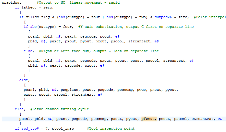
-
I have a post issue that I can't seem to fix. Undercutting in canned roughing cycles on a Fanuc control. It is graphically represented correctly in the backplot but the post doesn't add the Z value to the first line after the canned cycle to tell the control it's a type II cycle. It seems like it's just an error because the control throws a monotonous error until I add the Z as shown below. Mastercam Posts out this: And I need it to post out this for a type II cycle: Anyone have some insight?
-
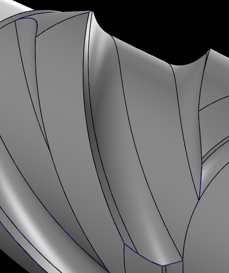
Trying to mill a helical blade into a stabilizer. Tool I want to use is a 2" Seco High Feed Mill, It's limited to a .02" Axial DOC, but can do the full 2" width. It can not side mill whatsoever. So with not being able to side mill the tool basically needs to be from the "top" but not. Geometry has a radius at the bottom and the tool is mostly flat, I basically need a 3D core roughing result, with the rotary axis thrown in for the helix. I've tried multisurface, flow, and multi-axis roughing none have worked, multiaxis roughing seems like what I want but it will not generate me a toolpath at all. Tried a whole shwack of different parameters. Anyone have any ideas?

-
Motorized Rotary table
sunderlandjoe replied to SpecialtyTool's topic in Machining, Tools, Cutting & Probing
I'm using two different mazak mills with rotary tables, they're made by kitigawa. They came with the machines though.