Bill Henderson
-
Posts
260 -
Joined
-
Last visited
Content Type
Profiles
Forums
Downloads
Store
eMastercam Wiki
Blogs
Gallery
Events
Everything posted by Bill Henderson
-
Thanks John. I had to repost my program to run on a Doosan DVF8000. Which resulted in a broken drill. R.250 Q.250 doh! My bad. Just assumed it would post a peck reduction. Luckily it was just a fixture.
-
The code I used to get would be like G99 G83 Z-1. R.5 I.25 J.15 K.1 F3.57 I : Initial peck J: Amount to reduce peck K: Minimum Peck
-
I was under the impression the G83 and subsequent peck would be used for that purpose. I find that it is not. So what is the subsequent meant for? My code using .250 initial peck and .100 subsequent : G43 H43 Z.5 G94 G99 G83 Z-1. R.5 Q.25 F3.57 G80 G49 M05 I could have sworn years ago I used it and the first peck would typically cover my retract distance and subsequent would be what I used in material.
-
We (our off-site IT) just did the install about a week ago and I started a new project today. Open new Step file. Once opened none of the F keys work (F4 analyze) (F9 AXIS Display) ALT F1 or F1/F2 ALT S ALT E I tried starting a new file and created wireframe and the same results. Is there a setting or file path that needs to be corrected?
-
I know Pete thanks. We did before I posted here. Was hoping there was something I was missing. Funny Matt. Still in Thee Circle I see..
-
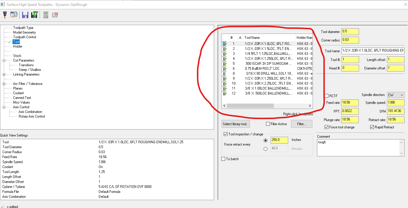
This is something that never really bothered me until MC added the holder libraries years ago. The tool window page in operations parameters is too small and not adjustable. They give you a slide to view the entire row, but why not make it expandable? Years ago you couldn't even adjust the size of the parameters window when it popped up. They added that feature a few years back but failed to add it to the tool window. Many times you have the same tool description with different length holders and to remember some 30+ tool/assemblies is difficult. Just make it expandable. Or am I just missing it?

-

Doosan DVF 8000 Verify/Post issue?
Bill Henderson replied to Bill Henderson's topic in Post Processor Development Forum
I don't have the code any longer. They re-wrote the program for indexed surface milling. These are one off inconel parts for R & D. You may have been here when the machine was first checked after issues. Yes it is bolted to a newly poured floor. Thanks James. Haven't heard from you since you left FB. Hope all is well. Tom thank you as well. Been a long time. Hopefully we will be able to use the machine to it's full capability but right now I have hardware that absolutely NEEDS to ship. -
Doosan DVF 8000 Verify/Post issue?
Bill Henderson posted a topic in Post Processor Development Forum
We recently purchased this machine new. First parts run on it had issues in tool offsets using dynamic. Post was verified and it ended up being some parameters or interpretation software error. Thought it was fixed and finally made a good part. Now my parts are on this machine and an off-site programmer made the programs. The verify in simulation looks correct in 5X swarf etc... but in reality my part is scrapped. Wall thickness which is supposed to be the same at various points is very narrow. G59 G17 G90 A-90. C180. G68.2 X0. Y0. Z0. I-180. J-90. K0. G53.1 G94 G05.1 Q1 R5. My question would be ... could the tool vector be calculated wrong at the machine? The code looks correct and simulates correctly. Seeing the tool offsets were being calculated incorrectly before and it took Doosan reps 10 days to figure it out, I am wondering if it's just the machine again. BTW He programmed the pieces to center of rotation. I haven't been on here in years mainly due to the fact I rarely if ever have to program anymore. Thank you for any insight. -
Thanks Daryl. Will look into them.
-
"Bill - that material looks like a cutting tool graveyard!" That it is! Had a meeting yesterday trying to explain to the bean counters why we are using so much tooling $$$.
-
Thank you everyone for your input. The Doosan cutting 303/304 I wouldn't guess to be an issue, but this material ... Nominal Composition Nickel - 52% Cobalt - 20% Chromium - 20% Molybdenum - 6% 2.4% Titanium - 0.6% Pretty nasty. I am pushing for the Makino.
-
Thanks guys. Yes I like and Prefer the Makino. We had a salesman in here very nice machine indeed the A81. I think our bean counter is still dizzy by the estimate. Doosan? I am looking for one reply on the doosan good or bad. Trying to tell our Program manager they aren't worth it.... but you know... he has done and seen everything. On a small Inco part after I designed the fixture for HMC he said.... Use the HMC clamp here (the bottom) and use a center over the top and you can cut the whole part spinning it 360. "We used to do this all day long"
-
We have a LTA for some Nimonic 263 material approx 2"X 11" X 23" type frame. Currently running 3 AXIS and using two fixtures (MO and Clamp movements) on a CAT 50 HAAS. (don't laugh) Incredibly long cycle times and tooling costs per part. Owner(s) have agreed to purchase a slightly used machine. I want ceramics for slotting to improve cycle times (currently eating up 80% of cycle) I want Horizontal multiple pallet for increased fixturing (more parts) and chip evacuation. I want tool life cycle management, probing, rigid machine, and HP. Given a low budget to work with 200K-400K Would you go with a DOOSAN that is newer (2015) or a tried and true Toyoda (2008) or Makino (2008)? I have never had much luck with Doosans running more that 75% of the time without some need for fixing. The HAAS will not hold up cranking these parts out 2 shifts 9 hours a day 6 days a week. What do you say? Any experience with Doosan cutting Super Alloys? Thanks. Any input greatly appreciated.
-
X8 Limiting Axis windup
Bill Henderson replied to Bill Henderson's topic in Post Processor Development Forum
Thanks Colin I will try that. I didn't set wind up limits btw. I did however have to set Mi 8 to 4. It was set to 1 and at the end of the swarf single pass (cutting Y- side of trunnion) it would retract to Z7 reposition X correctly but turn Y to positive Z rapid into trunnion and then make the correct Y- move to position of start of cut. Scared the crap out of the operator. -
X8 Limiting Axis windup
Bill Henderson replied to Bill Henderson's topic in Post Processor Development Forum
ha ha. John that would make TOO much sense. Thanks John. That's it. What was I not thinking? -
I have a swarfing cut making multiple passes. I am using the Generic HAAS 5X which has been modified for axis label output. (thanks Colin) The initial axis rotates between -45 and -90 degrees while the (A) axis turns completely in circles.. X-.0176 Y-2.4001 Z1.8735 A-2154.67 B-89.868 X-.0121 Y-2.4009 Z1.8726 A-2156.32 B-89.927 X-.0065 Y-2.4015 Z1.8725 A-2157.97 B-89.969 X-.001 Y-2.4018 Z1.8733 A-2159.619 B-89.987 After several passes the A is wound up to 2159 degrees. Is there a way to limit this? I have tried here.... #Set pri_limtyp and sec_limtyp on following conditions #0 = Less than 180 degrees #1 = Equal or greater than 180 degrees and less than 360 degrees #2 = Soft limit at 0-360 degrees with hard limits slightly beyond #Set limhi-limlo to hard limits, inthi-intlo to 360 degrees total #limhi-limlo are expected equal amount from inthi-intlo #3 = Greater than 360 degrees auto_set_lim : 1 #Set the type from the angle limit settings (ignore these) pri_limtyp$ : 0 sec_limtyp$ : 0 #Rotary axis travel limits, always in terms of normal angle output #Set the absolute angles for axis travel on primary pri_limlo$ : -9999 <<<<<<<<<<<<<<< HERE pri_limhi$ : 9999 #Set intermediate angle, in limits, for post to reposition machine pri_intlo$ : -9999 pri_inthi$ : 9999 #Set the absolute angles for axis travel on secondary sec_limlo$ : -9999 <<<<<<<<<<<<< HERE sec_limhi$ : 9999 #Set intermediate angle, in limits, for post to reposition machine sec_intlo$ : -9999 sec_inthi$ : 9999 But that posts an error Could it be somewhere in here? vvvvvv #Tolerance settings for wind up p_tol_ang : 210 #Primary angle move to exceed for direction change s_tol_ang : 210 #Secondary angle move to exceed for direction change d_tol_ang : 210 #Dummy angle move to exceed for direction change #pri_limtyp = 1, tolerance to validate tripping limit # reset the p_frc_adj_sec flag when back to normal range #pri_limtyp = 2, angle move >= to trigger reposition on primary and # angle move >= with rev5 or 180 reposition to validate tripping limit p_rsoft_tol : 45 #sec_limtyp = 2, Angle move >= for reposition s_soft_tol : 270 adj_lim_trp : 90 #Angle move in p_pri_rot180 to trip reposition #pri_limtyp = 3 and sec_limtyp = 3 control values p_rsoft_tol3 : 90 #Angle move >= with rev5 or 180 reposition Any input would be greatly appreciated. Thank you.
-
For Bill H. - Swap Rotary Axis Label
Bill Henderson replied to Colin Gilchrist's topic in Post Processor Development Forum
Very good thanks Colin... again. -
Swap axis label
Bill Henderson replied to Rocketmachinist's topic in Post Processor Development Forum
I have searched but to no avail. I know this should be easy Colin, I have done it numerous times but seem to be forgetful. I need to change primary "A" axis to "B" and "B" to "A". And make "B" which is rotating about X Axis toward operator (negative). Geesh I wish my memory was better. I was able to limit the axis output to prevent winding up. Thanks for your help in advance. -
Yes, that was our intentions, but GO GO GO.... I have contacted Kennametal tech support to see what they can come up with. Thank you.
-
I figured it was high, but a miss quote by about 6 hours machining time a part. :/ Thanks.
-
I have slots width(s) varying from .140 - .170 with .04 rad and depth of slots (deepest) .560 Rigid setup but it is on a HAAS. Length of travel around one slot is approximately 55". Material as in the title Nimonic 263. I have tried large diameter Ingersol slotting tool (.125 X 3" 5Teeth) with carbide inserts. Running full depth for roughing. 145 RPM .0015 CLPT at F1.1 (SFM 114) Then I finish with a 1-1/2" X 10 teeth Carbide Keycutter coated. <<<< this is special made cutter because I can NOT find an insert cutter with the radius requirements>>>which makes the neck very thin. This tool is running 216 RPM .00093 CLPT at F2.0 (SFM 85) Seeing there are two slots at 55" the mill time is enormous. Does anyone have a really good slot cutting source where I may find inserted cutters that offer .04-.05 radius? Or any ideas as to how we can run this part faster? We do NOT have probing so operator has to constantly monitor these passes. The folks who quoted this never have dealt with Demonic 263 and are aghast at the feedrates. Our profiling is running around 140 SFM using Ingersol insert tooling. Any ideas or thoughts would be appreciated. Thanks.
-
Is there a way to change the layout of the operations pop up? The window on the left side is wasting space but the window on the right side (tool list) is so small you have to scroll across to see more tool info. Seems a bit backwards to me. If not, could this possible be changed in future versions? I use a lot of variations in tool length of the same tool and the tool length is hidden further to the right. Not a big deal just seems like the layout is a bit odd.

-
Forget it. Figured out I had a solid sheet. That's the problem when working half in solid and surfaces.

-
Incorrect cycle time in Active Report
Bill Henderson replied to Bill Henderson's topic in Industrial Forum
Hi Mick, Here is what the XML has... and for some reason it is picking LONG -<NCFILE> <SPACER>SJV</SPACER> <NCIFILE-LONG>C:\USERS\BILLHENDERSON\DOCUMENTS\MY MCAMX8\MILL\NCI\BASE PLATE OP1.NCI</NCIFILE-LONG> <NCIFILE-SHORT>BASE PLATE OP1.NCI</NCIFILE-SHORT> <NCFILE-LONG>C:\USERS\BILLHENDERSON\DOCUMENTS\MY MCAMX8\MILL\NC\BASE PLATE OP1.NC</NCFILE-LONG> <NCFILE-SHORT>BASE PLATE OP1.NC</NCFILE-SHORT> -<OPERATION> <SPACER>SJV</SPACER> <NAME>Peck Drill</NAME> <COMMENT>DRILL 3/16 DOWEL</COMMENT> <IMAGE>C:\USERS\PUBLIC\DOCUMENTS\SHARED MCAMX8\COMMON\REPORTS\IMG\OPERATION7.BMP</IMAGE> <COOLANT>Flood</COOLANT> <CLEARANCE-PLANE>1.0</CLEARANCE-PLANE> <COMP2TIP>NO</COMP2TIP> <DEPTH>-0.85</DEPTH> <FEED-PLANE>0.1</FEED-PLANE> <PROG-NUM>0</PROG-NUM> <RETRACT-PLANE>0.0</RETRACT-PLANE> <STOCK-TO-LEAVE>0.0</STOCK-TO-LEAVE> <TIME-LONG>1 HOURS, 9 MINUTES, 41 SECONDS</TIME-LONG> <FEEDRATE>5.1792 inch/min</FEEDRATE> <SPINDLE-SPEED>2158 RPM</SPINDLE-SPEED> -
I have done a search on here but couldn't find anything. I have some drilling cycles that put out some crazy times. In verify the run time is approximately correct. I have made my own report and most other cycle times are correct in the report except for these odd ball drilling cycles. I uploaded my report and if you look at Operation 8 it is one hole thru a 3/4" plate Feed rate 5 IPM with .10 pecks. I am wondering if I have something askew. Thanks for any insight. Dawoo DMV3016.pdf