khass0410
-
Posts
29 -
Joined
-
Last visited
Content Type
Profiles
Forums
Downloads
Store
eMastercam Wiki
Blogs
Gallery
Events
Everything posted by khass0410
-
JoshC, thats pretty much what I wanted. That's a great tool that I've never used before. I could not open your example file because of the education only, Thanks again. Just saw the pictures, appreciate the time you took to show me a couple different ways. What I originally ended up doing was creating a surface with draft turning the surface into a solid and boolean/remove the solid from the part.
-
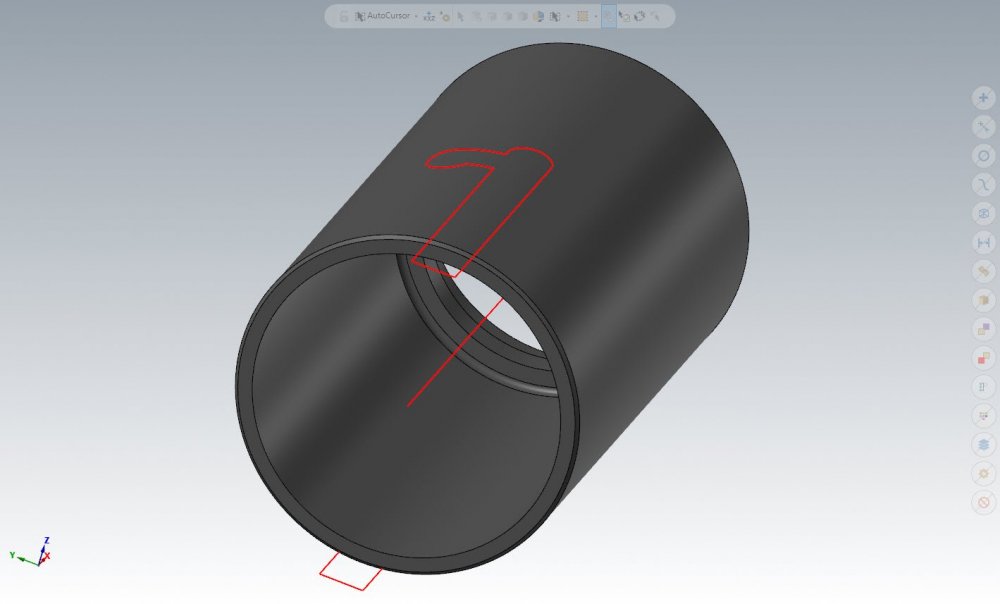
I’m not sure that projecting it flat will give me the results I’m looking for. I need that hook to be on the angle that it lie’s around the cylinder…… not sure I worded that correctly. I’ll project and cut it again just to make sure.
-
Hi all, thanks for the help in advanced. I've rolled some flat wireframe geometry around a cylinder. I'm now trying to figure out how to extrude/cut the wireframe through the cylinder. Considering its not flat I can't just extrude. Is there an easy way of doing this? Only thing I can think of is to create lines to the center of the cylinder, find the angle and extrude cut at that angle. In the attached pic you'll see my solid and wrapped wire. Thanks again.
-
So I just changed that. Didn't realize that setting was for that. I'm still seeing a small gap between the insert and part. Maybe I'm being to picky? 2021-06-10_15-46-30.bmp
-
Just downloaded them. Will watch soon. Thank you.
-
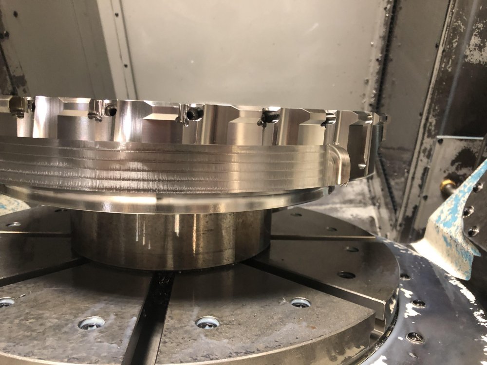
Hi all, thanks for the help in advance. I downloaded our Lathe cut off tool holder and insert from the Iscar website and have been trying to make a Lathe 3D tool work. I think I am fairly close. My problem is when I backplot the insert is not making contact with the part. If I use a Lathe standard tool with the same toolpath everything looks correct. The attached file is the Lathe 3D tool making no contact and the standard tool making contact with the same toolpath. Any help or advise would be appreciated. krh - 3D Tools.mcam
-
Ron, Thank you. This is what I was needing. I've been in contact with my reseller. Just wanting to make sure that it was a post related problem. Hopefully they can fix me up. Ron do you mind me emailing you about something you helped me with in another topic?
-
I just tried that after you mentioned it and nothing happened. So if I remember correctly MR1 in the post is based off of MR6, If MR6 is disabled in the post it will look at MR1 and apply it to all toolpaths.
-
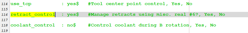
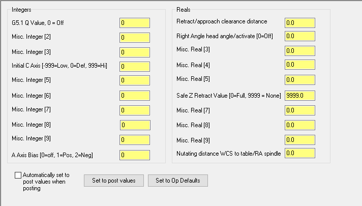
This is a MLC post, so my Misc. Values page is a little different. My MR6 is a Safe Z Retract and when I turn it to None it does keep the tool down during multi-passes but say I'm doing more then 1 pocket when the tool is done with the 1st pocket the tool won't return home it stays down because the Safe Z Retract is set to None.
-
So I tried creating a new curve 5 axis toolpath with the Safety Zone and I'm receiving the same code as I was before with the tool returning to Z0 before making the second pass. So maybe it's my post? Or my post is ignoring the safety zone? I agree about the dumb downed solid I do have one but didn't create my toolpaths off of it. The file I sent was just a small bit of what I have in it. Thank you for the help.
-
Hi everyone, Hoping yall can help me figure out if i'm doing something wrong or if it's my post or if I need a post modification. I’m using the toolpath Curve 5 Axis with two passes in multi-pass. For every pass it makes the tool goes home in Z “G0 G28 G91 Z0.”. Is it suppose to go home for every pass? I would think that if “Keep tool down” is not checked the tool would retract to its clearance plane and reposition for lead in and out and if “Keep tool down” is checked it would not retract to its clearance plane but stay down and reposition itself and carry on. If you open up the attached output you will see the tool going home around line 359. The attached file has 3 toolpaths within it… The 1st Operation has keep tool down checked, the 2nd Operation does not. The 3rd operation is in a different tool group and is for the pocket on the opposite side so I would expect if Operation 2 and 3 were posted out together for the tool to go home before moving to Operation 3. I am also using Swarf Milling, Morph, & Multi-axis Rough with multi-passes and depth of cuts and these toolpaths do not go home until they transition to another pocket. Thanks for the help. CURVE_5X_TOOL_RETRACT.mcam KEEP TOOL DOWN OFF.MIN KEEP TOOL DOWN ON.MIN
-
I'd like to let yall know that that endmill from Sandvik worked GREAT! The cut is super smooth, looks weird but very smooth. Thanks again.
-
I got the difference between G43.4 & G68.2 down. Now for the other stuff you explained I will probably have to read over it 10 to 20 times plus some just to wrap my mind around it. I want to say they were teaching this in one of the Emastercam lessons but I can't remember. Ron, thank you for helping me out and going in depth on how this works, I'll definitely work on it and use it.
-
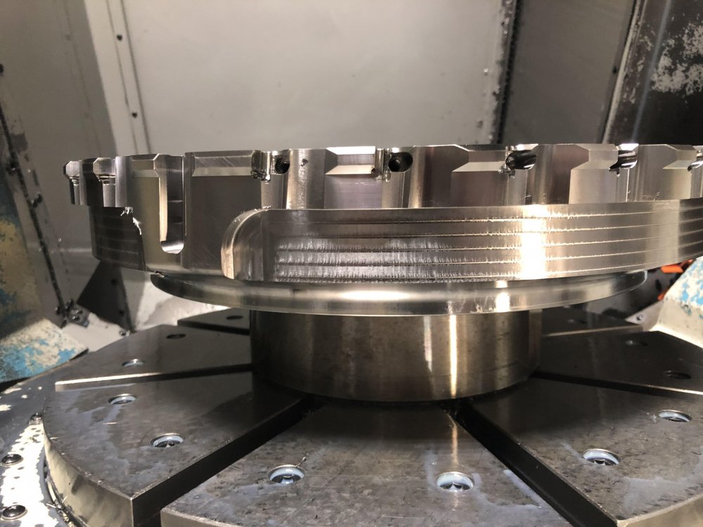
So the machine we are running these cutters on is a Makino D500 with A and C axis and we use G43.4 mixed with G68.2...... Will axis substitution work with G43.4? or is it meant to come from exact center of pivot? I'm not exactly sure how you set up axis substitution either, I think I have to use the Xform "Roll/Unroll" function to unroll my geometry but when I do it in my main view "how the part is sitting in machine" than I get odd twisted up geometry. I can mimic what you did in the front view but am sort of lost on doing it in my base view....... I will continue working on it any hints would be great though. Also work is going to order a couple of them Sandvik Endmills that David Colin mentioned, pretty excited about this. Thanks for all the help you guys.
-
Thanks for sharing the information, this will be a great resource. I'll have to look up their cutters price range but I can imagine it's going to be more than what our shop will want to pay. lol. But, thanks for showing me what I should be looking for.
-
Ron, thanks for the replies. I came really close to bringing up that the tool I'm using is a center cutting endmill. I was wondering if that could of been the problem, I appreciate the explanation on what is going on. This is a cutter that we are making for a customer, when putting weight reduction on a cutter this is not typically what we do but this is what they want. I agree on the with the bigger fillets. I forgot to put one of Schunk holders on the tool when sharing the file, I sometimes use the holder avoidance tool inside the parameters, so normally I have my holders set up. The other part that I was working on when having the same problems, I ended up using the multiaxis roughing op to finish. I never even thought about using axis substitution with dynamic milling that's brilliant. Thank you for the help and great ideas.
-
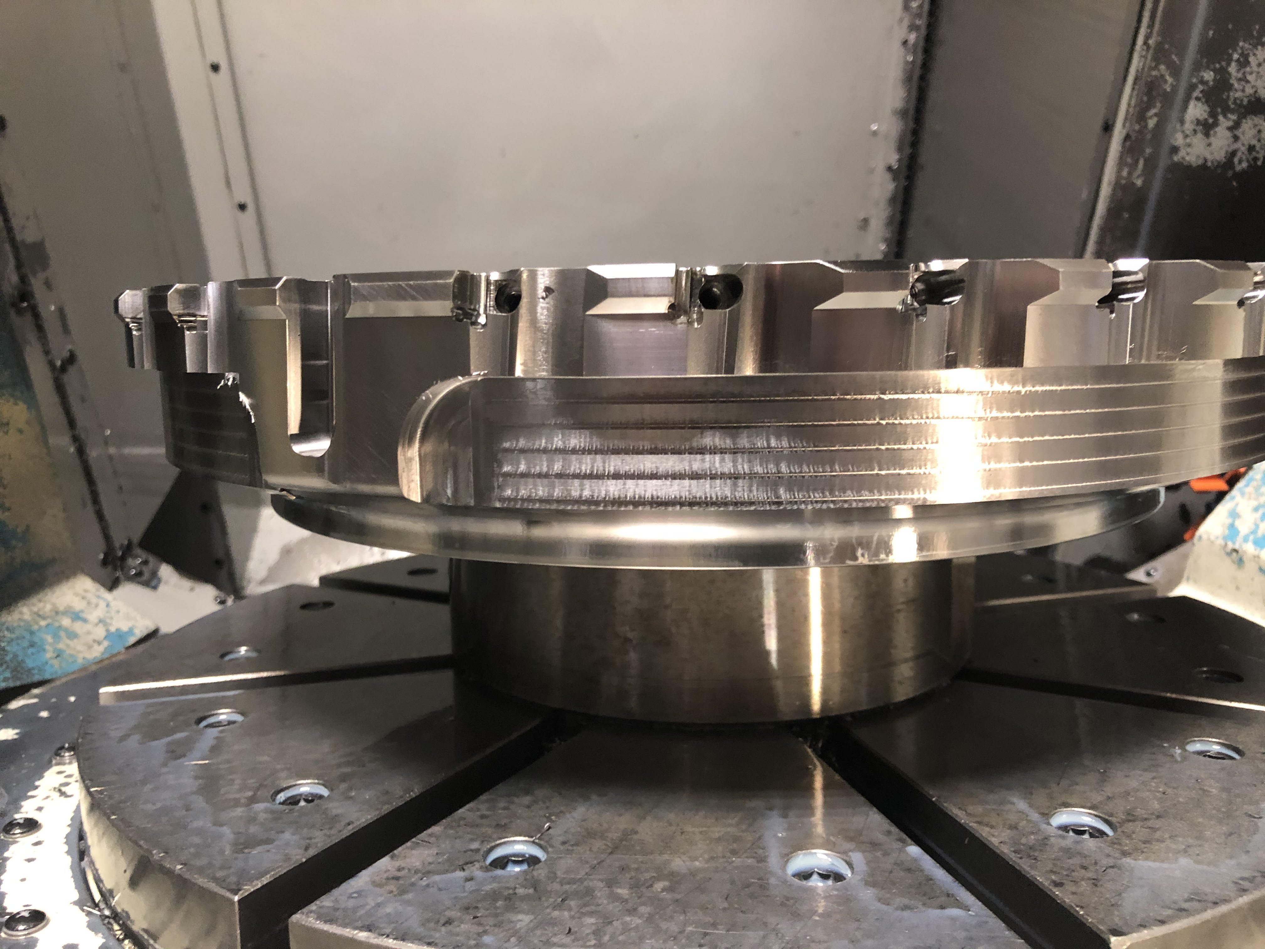
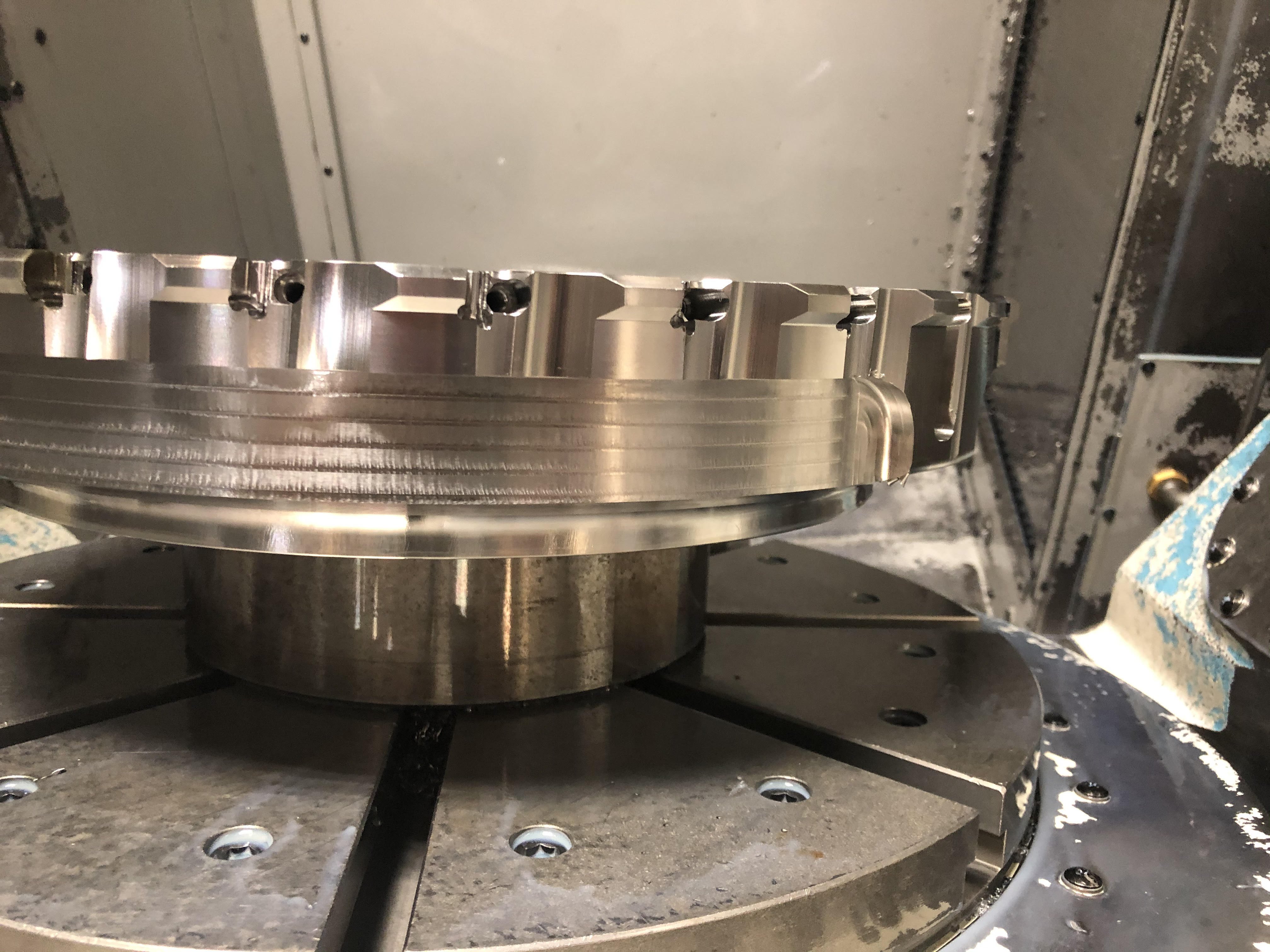
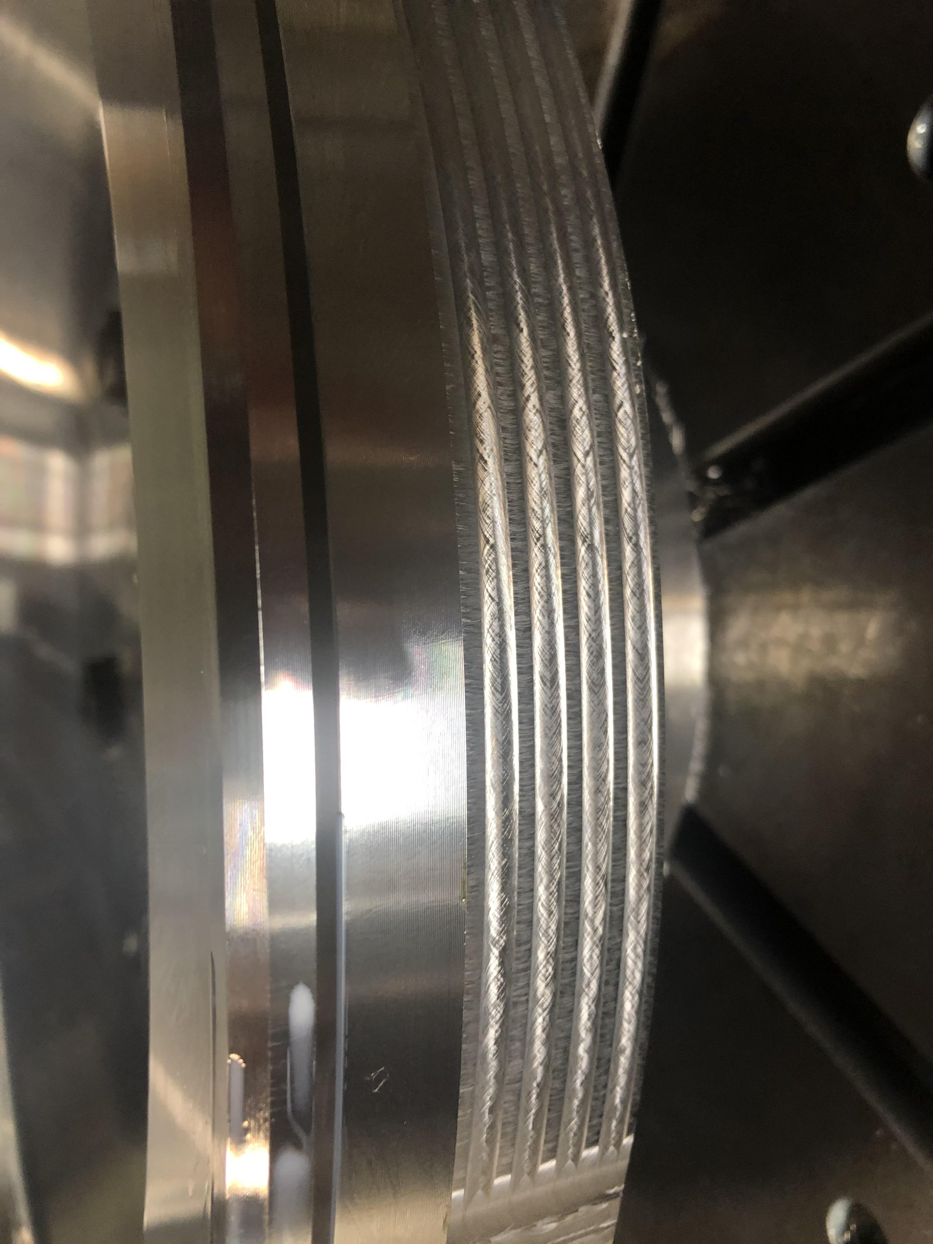
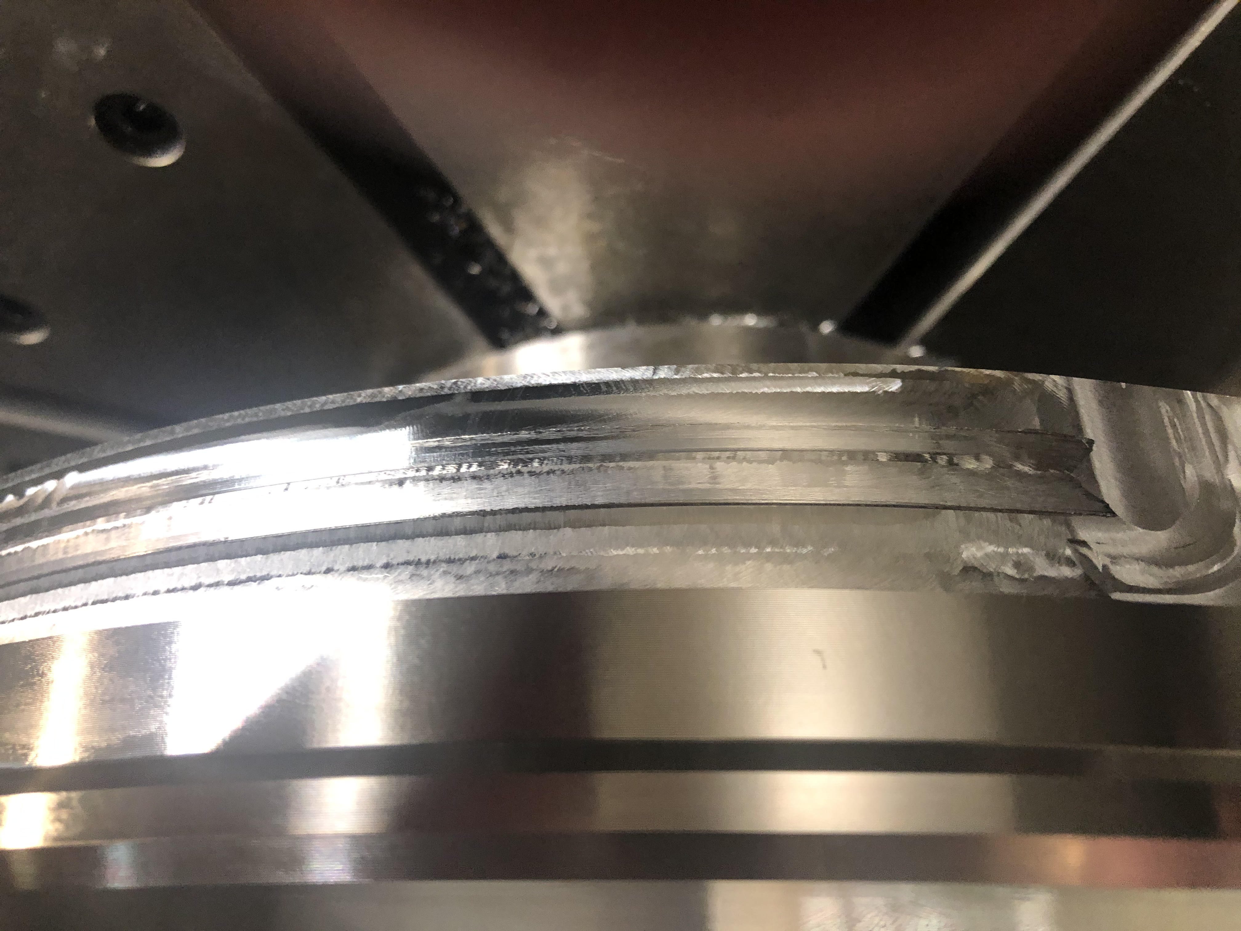
Hoping someone can tell me what I'm doing wrong or why I'm not getting the results that I am wanting to get when using the Curve 5 axis toolpath. I've tried using the Curve 5 axis toolpath in the past but I always get steps in between each step over on my parts when using multi-pass. I'm using the bottom of the endmill with plenty of overlap while rotating C axis. The machine this is running on is a 5 Axis Makino D500. I've attached a couple pictures. The first picture is when I tried using a 1/2" .060R Mill with a step over of .250" 5 times. The second one is when I tried using a 1.0" .060R Mill with a step over of .500" 2 times. I've also attached my file just in case someone wants to see what have in the parameters. I'd really like to figure out what I'm doing wrong because I normally resort back to using a 3d surfacing toolpath to get the results that I need. Thanks for the help.


-
I believe you have to use the link that Jessica Thompson sent over to access the videos being that it is a temporary deal for the ones that purchased the class.
-
Using MI1$ to set up macro call line
khass0410 replied to khass0410's topic in Post Processor Development Forum
Awesome, I found it, seems like a lot to add but I'll give it a try. Thanks again. -
Using MI1$ to set up macro call line
khass0410 replied to khass0410's topic in Post Processor Development Forum
Any hits on what to search for? Is it the one you did for the Calling a Pallet? -
Hi everyone, I'm trying to have my post setup a macro call line for my machine rotations every time the tplane is changed using the MI1$. I need it to output in the beginning of the program, but I don't know how to do this is there a loop process or somewhere I can put this to make it out put it correctly? At the beginning of my program output looking like this with the G65P9013 lines setup % :0001(FIXTURE - COPY 111) (PART - FIXTURE - COPY) (POSTED - 04-17-17 8:00 PM) (MACHINE - FEELER) (T1 - 1/2" EM) (T2 - 3/4" EM) (T3 - .281 CENTERPOINT DRILL) G65P9013A#600X0.0Y0.0Z0.0 B45. A90. G54 <<<<<<<P9013 is are macro that defines COR B45. & A90. is the rotation that G54 work offset uses G65P9013A#600X0.0Y0.0Z0.0 B28.22 A74. G55 G65P9013A#600X0.0Y0.0Z0.0 B28.1 A90. G56 G20 G0 G17 G40 G80 G90 G94 G98 G0 G28 G91 Z0. G0 G28 G91 Y0. T0 M6(** T0 - NULL TOOL **) M26 M40 G0 G54 G90 X0. Y0. S0 M5 G56 B45. A90. M25 M39 G43 H0 Z0. G0 G28 G91 Z0. G0 G28 G91 Y0. Here is what I have in my post......Not much, I did have a lot of other stuff in there but I was really confusing myself... It may take a lot more then this, i'm new and haven't really made it this far into editing code. I have it posted under the psof$ .....It posts out for the 1st tool but not the second or what if I switch rotations using the same tool? if mi1$=1, "G65P9013A#600X0.0Y0.0Z0.0",*p_out,*s_out,*pwcs,e$ Any help or the lead into the right direction would be great. Thanks everyone
-
VERISURF TOOLS For MASTERCAM 2024
khass0410 replied to Verisurf - Ernie Husted's topic in Industrial Forum
Maybe you can show me an example on how to get it to work with sheet solids or wireframe? I can get it to work in some of the older versions of Mastercam but I can't get it to work in Mcam2017 -
VERISURF TOOLS For MASTERCAM 2024
khass0410 replied to Verisurf - Ernie Husted's topic in Industrial Forum
I tried using the hole axis under model prep, I think it's for solids only. I tried creating solids from surfaces and it turned my part into a sheet solid which it still did not want to work. Other than that i'm assuming that it won't allow you too snap on to wire anymore. Thanks y'all. -
VERISURF TOOLS For MASTERCAM 2024
khass0410 replied to Verisurf - Ernie Husted's topic in Industrial Forum
Anyone know if the free verisurf for mcam2017 has been updated? I'm having trouble with the hole axis tool, I can select surfaces and it put a point to the center of the arc but when I try and select wire it puts it at the origin point. Thanks -
Thanks for all the responses. The drilling cycle was nothing but a example, there is a variety of stuff that gets changed day by day. Again thanks for all the replies and will def. try and use this information in the future.