lowcountrycamo
-
Posts
247 -
Joined
-
Last visited
-
Days Won
2


lowcountrycamo's Achievements
")


-

SWARF TOOL VECTOR DIFFERENT FOR EACH PASS
lowcountrycamo replied to lowcountrycamo's topic in Industrial Forum
Part came out beautiful. This Mag1 is a really nice machine. And the apps guys are the best I have worked with. The day we purchased this machine I was given a 200-page pdf outlining what they have found has worked and what has not. Vibrations analysis, RAH model numbers, RobbJack cutter catalogue for high HP/RPM mills, efficient toolpath use of accell/decell, etc. We purchased and I learned the Cut Pro software (tap test). We are having much success, and the owner is happy. Thanks again for the advice. -
SWARF TOOL VECTOR DIFFERENT FOR EACH PASS
lowcountrycamo replied to lowcountrycamo's topic in Industrial Forum
Gcode, I love this! I have tried to make Parallel work but could never get the tool to stay true to the wall. Many thanks for the help. -
SWARF TOOL VECTOR DIFFERENT FOR EACH PASS
lowcountrycamo replied to lowcountrycamo's topic in Industrial Forum
Gentlemen, much better! Thanks for the advice. -
SWARF TOOL VECTOR DIFFERENT FOR EACH PASS
lowcountrycamo replied to lowcountrycamo's topic in Industrial Forum
I would love to get your feedback. If this does not come through, I could try another way. Thanks TEST.MCAM-CONTENT -
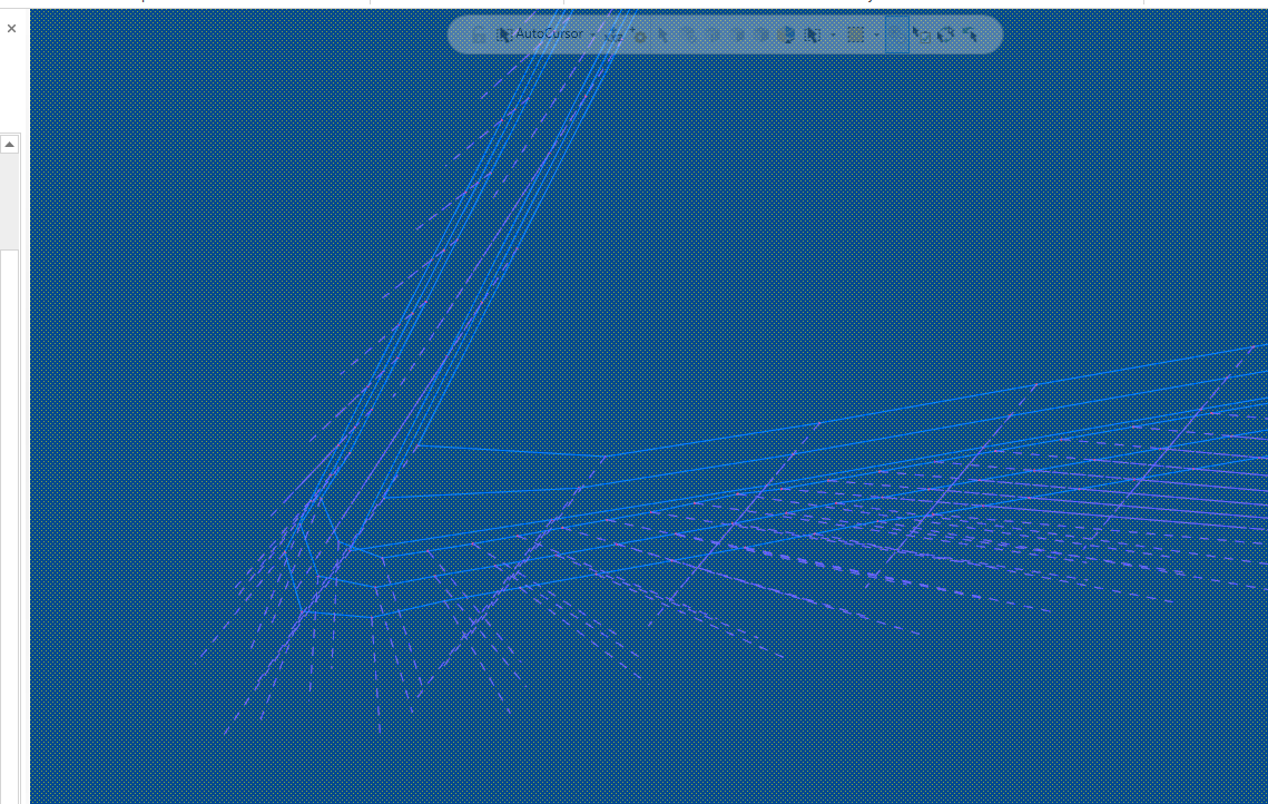
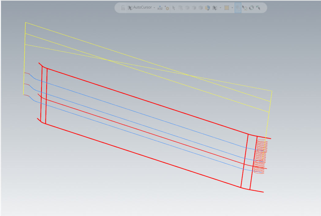
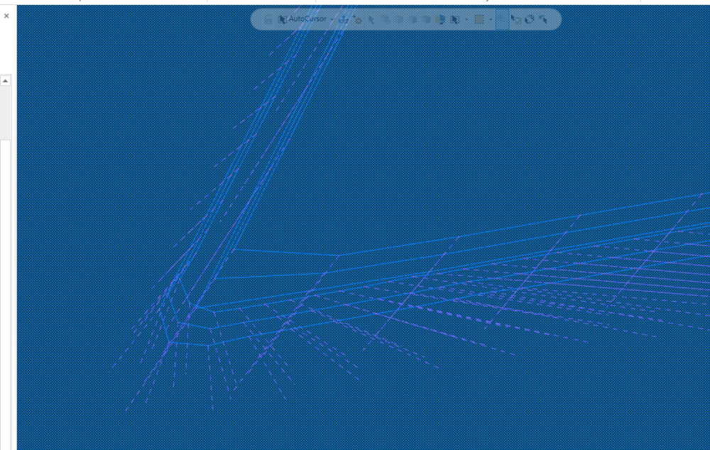
Hi Guys, We build mostly aerostructure and I use mostly swarf to finish part walls. I am always fighting the tool vector. It will change for different z passes and offset passes. On this part I am using sync with upper and lower chains. I have a floor but no wall surfaces. But depending on the part I often use normal to guide and sometimes tilt line. Does anyone know why this is happening? See pic
-
We build a bulkhead for a business Jet. It's flat on one side with pockets on the other. In the past, we have scraped many out of TOL. from warpage. Recently, I re-programmed this part with success and little distortion. Constellium, our material supplier was impressed with the part and asked to purchase one of these to take to the show. Of course, we requested permission from the OEM. They did grant permission as well as instructions to modify the part and rivet a name plate. This was displayed in there area of the Paris Air Show 2023. I am proud of this work. Thanks for reading, Steve Austin

- 4 replies
-
- 21
-

-

-
I get gouges and sometimes the cutter will just take out a wall. I do see this in verify and fix by breaking up edges in separate paths.
-
having problems getting good code for a head table mag1
lowcountrycamo replied to lowcountrycamo's topic in Industrial Forum
The problem appears to be Vericut according to Makino apps guys, who are 1st class in my opinion. Thanks for all the help! steve austin -
having problems getting good code for a head table mag1
lowcountrycamo replied to lowcountrycamo's topic in Industrial Forum
-
having problems getting good code for a head table mag1
lowcountrycamo replied to lowcountrycamo's topic in Industrial Forum
Thank you for that. I tried inserting a x0. In a dozen lines and running that to no help. Then I realized with G42.4 the coordinates rotate with B. Therefore X should start at 0. And climb to X12., right? Although your code does not show that so I am confused, I thank. -
having problems getting good code for a head table mag1
lowcountrycamo replied to lowcountrycamo's topic in Industrial Forum
T7 M06 M236 M238 M251 M11 G54 G90 A0. B90. X0. Y24. S1528 M03 G43.4 H7 X0. Y24. Z14.005 Z6.105 G94 G01 Z6.005 F27.81 <--- tool rotating around this point but should rotate around B axis center line. B89.048 F265.35 B88.0958 B87.1433 cutting B-88.0976 B-89.0503 B-90. -
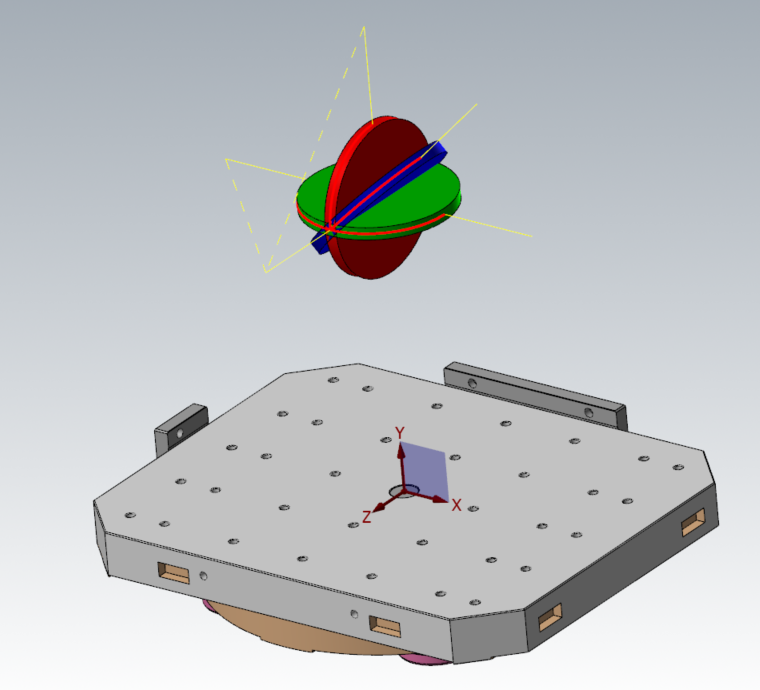
I have a postiblilty post for our new mag1 makino. They have been very responsive. I cannot get good code. This is a Fanuc Head / Table mill. I have been going back and forth with my Reseller. I am curious if I am programming this correctly. In one of Collins classes, he said the easiest way to prove a post is to create simple arc. So, I did that. When running a 5x curve around the green disk (B axis only) G43.4 does not work as the tool is rotating about the entry point, not around the disk. If I run around the red disk G43.4 does work as that is the A axis (Head) only. I am testing this code on a Vericut sim. I have programmed for head/head G43.4 and table/table G43, and have never had problems like this. Has anyone had any experience with this?
-
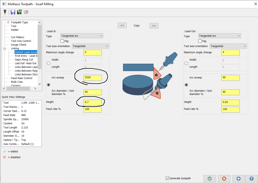
I have wished for a helix into contour often and I just tried it using swarf. I guess this would work with any of the module works paths. I set helix angle to 360 x 7=2520 and height to .7"

-
Best Extended Reach Tools for Milling?
lowcountrycamo replied to [email protected]'s topic in Industrial Forum
I have noticed on all 10 2.0" AXD we have is that they measure 1.990 - 1.992. I have asked out Mits rep to find out why and he came back with shrugged shoulders, "maybe to compensate for runout?" I finished walls with these occasionally, so I started modeling them to that size.- 37 replies
-
- 2
-
-
- long reach
- extended reach
- (and 1 more)
-
In the past I have drill corners on deep pockets but have gotten away from that. Not sure why. does anyone here practice that? I have also heard of plunging corners as well. thanks, steve austin