ScottBro4
-
Posts
55 -
Joined
-
Last visited
Recent Profile Visitors
533 profile views

ScottBro4's Achievements
")
Newbie (1/14)
11
Reputation
-
Get the solid model out off of the online catalog of the tool manufacturer. Most companies you can download it for free. Then just merge it into your file and create it as a custom tool. quickest and easiest way.
-
Lathe Spindle RPM set before Tool change G96 active
ScottBro4 replied to abc's topic in Post Processor Development Forum
I personally have never had luck getting this to work the way you describe. This should be possible but would most likely be done through the post. -
Milling chuck and stick-out
ScottBro4 replied to Matthew Hajicek - Singularity's topic in Machining, Tools, Cutting & Probing
Easiest fix if you're just roughing, grind a flat and put it in a solid holder. -
Hi Stephen, I work at CNC Software and we have an ST20SS which also has a Y axis. We use the G53. We have a post that works for our machine and we generally like to be involved with schools so contact our sales department and we will see how we can help.
-
Regardless of material, with the right feeds and speeds this part will not bow that much. Unless this is for a customer and there is a flatness call out I personally wouldn't be worried. In the end it will be sandwiched between 2 flanges and that will pull it flat. Just my opinion and experience with parts like this.
-
You could try using a waterline instead. It works similar and you can control your Z limits better which could prevent the retraction. I've run into the same issue.
-
I have done parts pretty similar to this.There is a pretty simple but somewhat pain of a way to done this accurately. Finish thru hole from one side, face, drill and tap bolt holes. Make fixture to hold the part down with bolts and locate off ID features. Cut profile and surface the other face on angle. Then, without removing from the fixture, cap over the ID and drill the tapped holes out. Good luck.
-
there was no 2016.
-
It is for anyone with a licence.
-
This is currently being worked on.
-
I have used the box thread in the NC code format on a Haas ST20 SSY. Works perfect.
-
Pitch in your little gems that make mcam life easier
ScottBro4 replied to jlw™'s topic in Industrial Forum
I don't know if anyone mentioned this or knew it but you can also customize key mapping in the settings. -
Getting a version with a basic Mill and Turn would be a good start. it will really depend on the type of work and machines you have. When and if you contact your local reseller, ask them about MastercamU. MastercamU is an online training course and is a very good starting point and covers a wide variety of Mastercam features walking you through step by step with verbal instruction. Any other questions just ask. Good luck.
-
Chuck Jaw parameter capture
ScottBro4 replied to Brian Pallas's topic in Post Processor Development Forum
I'm not sure I fully understand all that you're asking. As far as Z positions of your stock to the face of the jaws, that distance on the main spindle is controlled in the parameters but i usually control that length for the sub spindle within the cut off parameters. This can be controlled in the setup parameters but in the cut off op it will automatically transfer and copy all your geometry to the other chuck. As far as lines of code being in a specific location, that's going to be a post thing. Hope this helps -
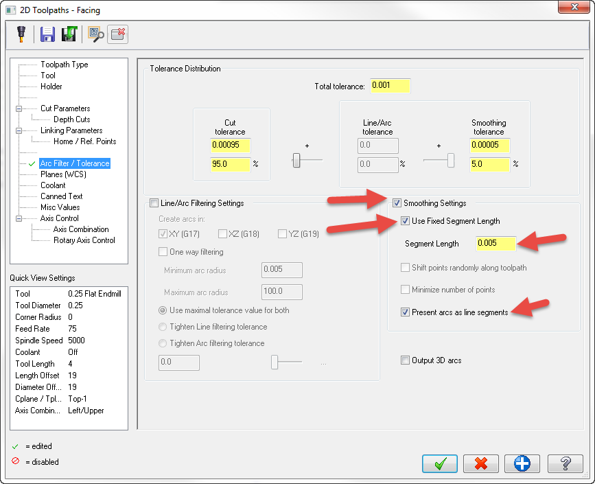
A simple solution is to go into your arc filter that is in almost every toolpath, check the boxes in the image below and you can adjust your line segments. not the best for finishing but works well on roughing.