Frank Caudillo
-
Posts
166 -
Joined
-
Last visited
2 Followers

Recent Profile Visitors
1,491 profile views


Frank Caudillo's Achievements
")
Newbie (1/14)
69
Reputation
-
Even with the Solidworks design tree, it still doesn't remember every single click or piece of geometry that was ever in each feature of the design. I can't imagine how many tens of thousands of clicks and iteration of geometry Mastercam would need to keep in a part file's history.
-
Just ran the benchmark on a new build for a coworker. 3 minutes, 20 seconds Dell Precision 3630 i9-9900k @3.6 GHz (boost up to 4.8 GHz) 32GB DDR4 2666 MHz RAM M.2 512GB Class 40 SSD Nvidia Quadro RTX4000 8GB Pretty snappy little machine.
-
Have you updated the drivers and verified that it doesn't work with your spacepilot? A few programmers in my shop are using discontinued models but were still able to get everything working in V9 with the latest drivers even though they didn't "officially" support their models.
-
I see. Well if/when you do start putting manufacturing stuff in there it would be cool to trade ideas and see what's working well for you. Feel free to PM me.
-
I know it's pretty belated but I just wanted to check in and see if you've had any progess with PDM and Mastercam. We've had PDM for our models and engineering workflows but I really think think the workflow automation can help with manufacturing data as well. If you've started storing manufacturing data in there what have been your pros/cons of implementation?
-
I would get G50 output that would cause a crash in Vericut on our Mazak when doing 3+2. The issue was when any plane other than "Top" (actual MC Top or a user created Top) had a different origin other than the Top plane it was using as the WCS. This would happen when moving fixtures and planes around a single part in the file. If I needed to adjust the fixture position I would shift everything and all but one of my planes was associative. Post it and then I would get a G50 that would try to shift the coordinate system by the difference between the index plane and WCS. Check all of your plane origins and make sure they're all the same.
-
Assuming you want this applied to feedrate, try adding the new format statement 18 below to your post. This should force up to 4 trailing digits for the first value (standard) and three for the second value (metric). Then, at your pmisc2$ postblock, update the new format statement from 12 to 18 (or whatever number you give to the new format statement). #Default english/metric position format statements fs2 1 0.7 0.6 #Decimal, absolute, 7 place, default for initialize (:) fs2 2 0.4 0.3 #Decimal, absolute, 4/3 place fs2 3 0.4 0.3d #Decimal, delta, 4/3 place #Common format statements fs2 4 1 0 1 0 #Integer, not leading fs2 5 2 0 2 0l #Integer, force two leading fs2 6 3 0 3 0l #Integer, force three leading fs2 7 4 0 4 0l #Integer, force four leading fs2 9 0.1 0.1 #Decimal, absolute, 1 place fs2 10 0.2 0.2 #Decimal, absolute, 2 place fs2 11 0.3 0.3 #Decimal, absolute, 3 place fs2 12 0.4 0.4 #Decimal, absolute, 4 place fs2 13 0.5 0.5 #Decimal, absolute, 5 place fs2 14 0.3 0.3d #Decimal, delta, 3 place fs2 15 0.2 0.1 #Decimal, absolute, 2/1 place (feedrate) fs2 16 1 0 1 0n #Integer, forced output fs2 17 0.2 0.3 #Decimal, absolute, 2/3 place (tapping feedrate) fs2 18 0.4t 0.3t #Decimal, absolute, 4/3 place (tapping feedrate) pmisc2$ #Canned Rigid Tapping Cycle pdrlcommonb #RH/LH based on spindle direction result = newfs(18, feed) pcan1, pbld, n$, *sgdrlref, *sgdrill, pxout, pyout, pfzout, pcout, prdrlout, *feed, strcantext, e$ pcom_movea
-
Do you have an example of code that is currently posting and that same code edited to how you want it to post out? Pretty sure this could be an easy fix.
-
Any way to make manual entry box larger?
Frank Caudillo replied to Tinger's topic in Industrial Forum
I usually will edit manual entry code in Cimco and then paste it into the box. Makes it much easier to read and catch mistakes vs that tiny box. If you have more than 750 characters you'll have to link it to a text file anyways. -
This has been my method as well. It works well and I have done this to split a model in half and then boolean add a different half to create a frankenmodel.
-
2020 processing times are seriously impressive. I'm still mostly using 2017 but when I do use 2020 it just feels quicker, especially with verify and stock models.
-
Thanks Chally. That makes a lot more sense now. I had never seen this behavior before now so I was pretty puzzled. I'll keep in mind for the future that dynamic might just need more info if I have any issues.
-
Maybe a silly question but are you re-clicking the Verify button from the toolpath manager after regenerating the toolpath?
-
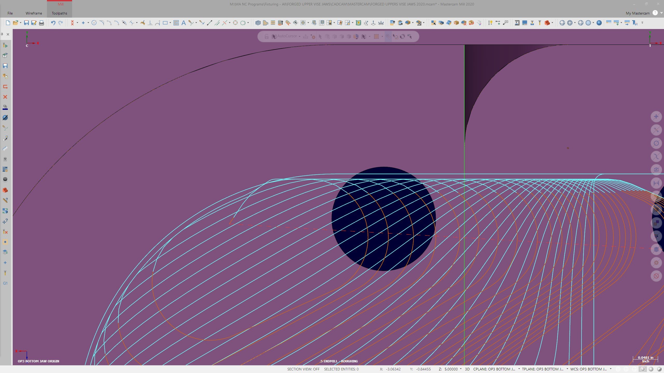
Total tolerance is .001". See the file for what's going on. When I created this example using the exact same geometry and toolpath settings I noticed that the problem goes away when only one "area" to rough/finish is chained. With all three sections chained you'll see the boundary violation behavior happen. DYNAMIC_BOUNDARY_VIOLATION.mcam
-
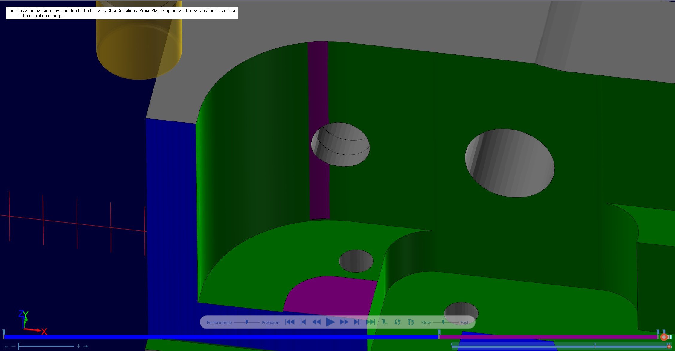
Came across this little surprise in 2020 just now. Dynamic path is violating the boundary when it leads off the material. The outer most path is a finish contour at 0 stock (Verify green) and the dynamic path violating it is leaving .01" stock on the wall (Verify purple). I can easily fix this by adding more stock to leave, but I feel like dynamic shouldn't do this regardless. Has this been a thing for awhile that I'm just now encountering?