RLeuschen
-
Posts
36 -
Joined
-
Last visited
Recent Profile Visitors
694 profile views

RLeuschen's Achievements
")


-
We had same issue. I added the following into the post at the header. If the program default isnt set, it auto sets it to "1" pheader_custom #Start of file "%", e$ !spaces$ spaces$ = zero if progno$=0, progno$=1, e$ *progno$, scomm_str, sprogname$, scomm_end, e$ e$
-
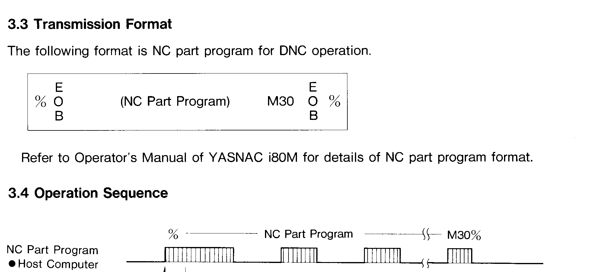
Leon, If I remember correctly, this had to do with a program stop signal. Used to happen randomly for us on an old yasnac on a mori lathe. I believe " % " was used for the start, and " % " was the stop.... Somehow... during drip, the tape interface would drop some characters and most of the time it was the % at the end. I'll try to find some notes I had for this Found one....

-
A couple months ago, Jeff started on the forum site about this. http://forum.mastercam.com/Topic36752.aspx#bm36788 I haven't heard anything on it again, until this. Looks lilke they started a "R-"
-
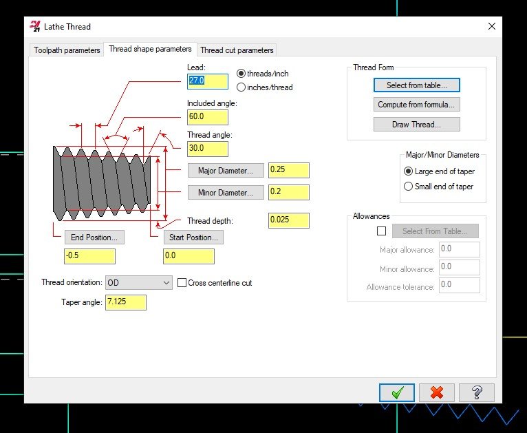
If your doing this in a lathe, I would use the threading cycle, select NPT type of thread, change the major diameter to .250 and minor to what ever depth of thread you'd like, set the number of threads/inch , and set angle to 7.125 degrees at a z ending depth of -.5. Depending on how deep you want the thread, you can adjust the major/minor diameters.. Hope that helps some, Rob
-
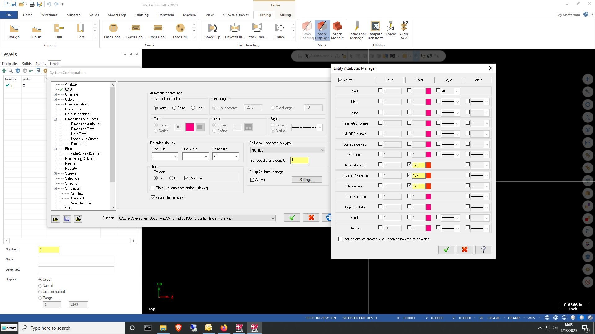
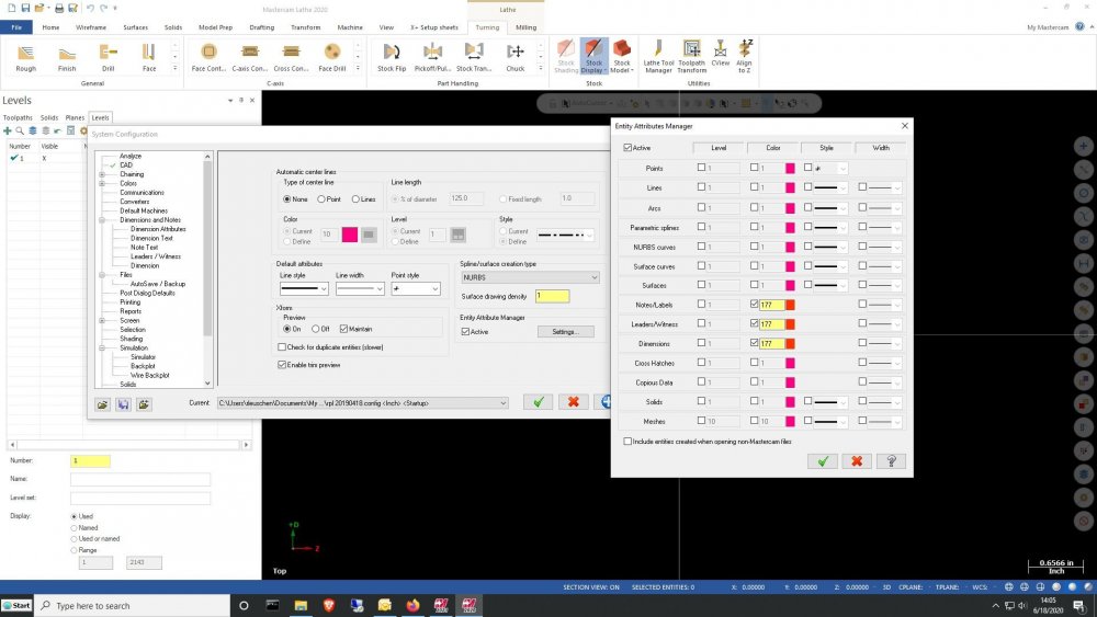
In 2019, 2020 and 2021 , you can go to system config, 'cad', then select 'entity attribute manager', and then click on settings. you can then set what entity colors you'd like.
-
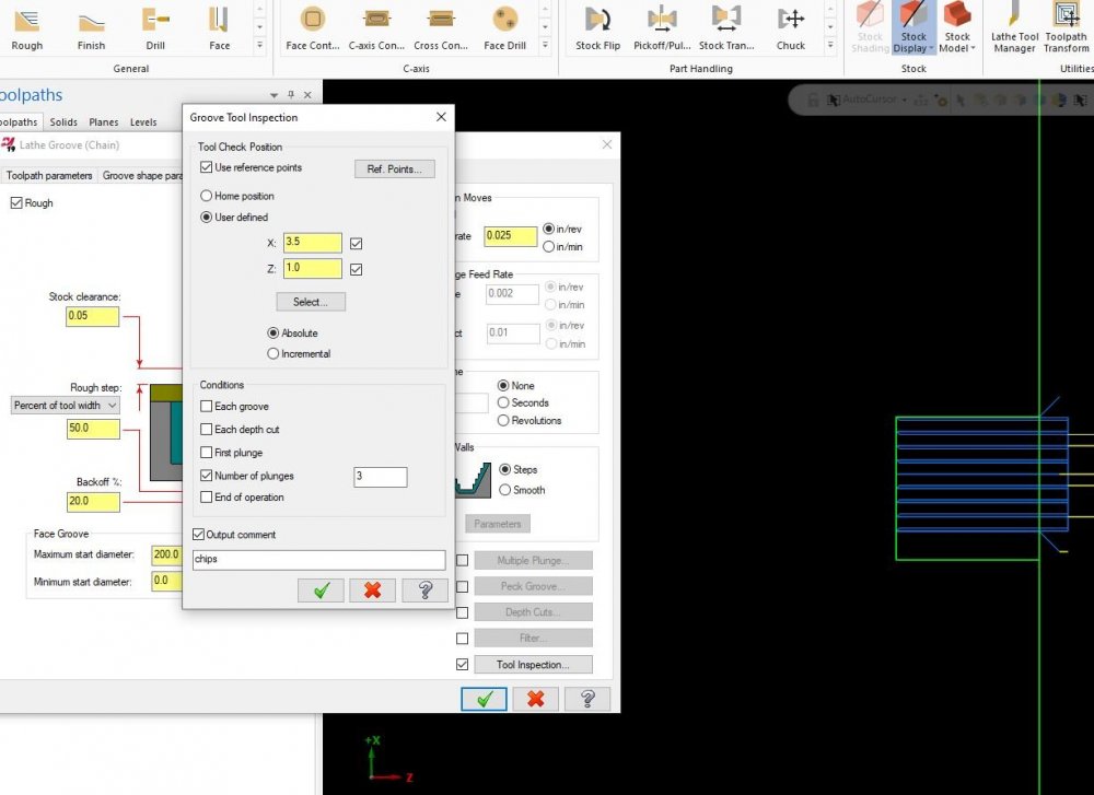
i just pulled a file from mc2019 to verify, but 3 posts that were in the library and the 3 custom posts we have, seem to support 'inspections'. I just threw this together to verity. If no value is put in the "comments" section ( i put "chips" in there) it will pull out the go right back to cutting without an "M00. your post as ron said, will probably not have that due to its age.
-
Can you share that file? I have both Okuma and Hwacheon lathes here. I'd like to see how my post reacts. You may definitely have to talk with your reseller if the post is the issue.
-
Ok ... as you wish. Currently hard turning, so my stock is equal to my solid geometry. Same toolpath, with a picco bore. running into a .56 major dia into a 1.5277 degree taper, going back z-0.9684. Test1.min has no reference point, test2.min has a x7. z1. reference point. test2.min test1.min .Min files are just text files from an Okuma.
-
I've been running mcam lathe since like version 6...not x6...(age showing now). IMO, Mcam has done some work to stock definition since then, and I've not had that issue ever again. There are alot of us on here that could help with this type of issue, maybe share a file and i'm sure someone can help.
-
Josh, Thanks for that info. But the issue seems to be with putting any value in the 'ref points - approach/retract values' that have to do with a rapid to x value. If any value is is x rapid, the g98 value is referenced from the rapid to point and not the clearance values placed in the linking parameters. I'm starting to think maybe something got upset in the post from having it converted over from 2018 to 2021.. See below: 2 examples: below with rapid values: T1010 G19 G98 M28 M8 M39 G0 G28 H0.0 (FORCE C HOME) G0 C90. G0 X5. Z1. (rapid points of x5. y0 z 1. ) Y0. G97 S2500 M103 G87 X-.05 Y0. Z-.7316 C90. R-.0625 Q25 P1250 F.5 M38 (this would be referenced from the X5 value..meaning it would clearance to x4.875 not the .625 as set in clearance values of the cycle) G80 X5. Z1. M9 M39 G28 U0 V0 G30 W0. H0. M105 below with out x rapids: T1010 G19 G98 M28 M8 M39 G0 G28 H0.0 (FORCE C HOME) G0 C90. G0 X.75 Z1. (no x rapid points, only y and z) Y0. G97 S2500 M103 G87 X-.05 Y0. Z-.7316 C90. R-.0625 Q25 P1250 F.5 M38 (this would be referenced from the X.75 value..meaning it would clearance to x.625 as it is in the linking parameters) G80 X.75 Z1. M9 M39 G28 U0 V0 G30 W0. H0. M105 T1000 thanks, Rob
-
I'm kind of interested in this, running mc2021 for c/y axis lathe. I Just had my cross drilling cycles ignore the clearance value (tried both ways with 'use clearance only at start and stop of cycle') and it wants to start the cycle from my ref points position. I don't remember this behavior in mc2018.
-
2020 Wireframe\Turn Profile\Slice now splines?
RLeuschen replied to ToddG's topic in Industrial Forum
I had similar issues previously in mc2020. I said something i believe last year. So far in mc2021 I have not had the issue. http://forum.mastercam.com/Topic33960.aspx -
DATUM QUESTION for Faro Arm Inspection/Verisurf
RLeuschen replied to haroldm9123's topic in Industrial Forum
Any chance you can show the 'feature control frame' and what your measuring in a little more detail? The datums on your pictures do not seem to be complete. As Aaron said, to create a line between points of a hole (top/bottom), would seem to mean its either an angled hole and everything is designated to the alignment of the angle at the -a- datum plane or its trying to prove perpendicularity on each measured feature . With no other controls/conditions listed, this would prove almost impossible to measure true positioning or anything else... without another alignment feature/datum. In GD&T, a lot of times a datum will have a specific control frame defining it (this might help)... Then again, some new designers seem to think we on the floor just know how its defined and then its off to the design room for a pow wow. It might be time to bang on someone's door for a little clearer 'feature control frame'. -
Jayson posted a response here. It helped me a lot with the same issue.
-
After some search time, I found it. Attached pdf is from an older set that I have, I believe they were Brown/Sharpe but who knows. Depending on the style/mfg of your triangles, this sheet could be incorrect. Its good that the students are getting multiple ways to check threads. But as Nickbe10 and 5th have stated, a lot depends on the class and spec of the thread when measuring. The root and/or crest of threads can cause more headaches than anyone could believe. Most asked question I ever get is, "how come my no-go fits, but go will not?". Most common answer is " check pitch, then check the root rad/root dia, and crest trunc" with the handbook values. Hope this helps, Rob thread triangle sheet.pdf